To determine the probability of the appearance of a flame, the main importance of the substances and various materials has a combustibility. This characteristic determines the category of fire danger of structures, premises, industries; Allows you to correctly select the tools to eliminate foci.
The combustion group of all material components of the object determines the success of fire combating, minimizes the likelihood of victims.
It is known that substances can be in various aggregate states that are important to take into account by defining a combustibility group. GOST provides a classification based on quantitative indicators.
If the substance can be lit, a combustibility group G1 is most optimal to fire safety than g3 or g4.
The combustibility is of great importance for finishing, thermal insulation, building materials. On its basis, the class of fire danger is determined. So, drywall sheets have a combustibility group G1, stone Vata. - NG (not lit), and insulated polystyrene foaming belongs to the combustible group of G4, and reduce its fire hazard helping the use of plaster.

Determining the gramificence class of gases and liquids, the standards introduce such a concept as a concentration limit. By definition, this is the maximum concentration of gas in a mixture with an oxidizing agent (by air, for example), in which the flame can spread from the ignition point at any distance.
If there is no such boundary value, and the gas cannot be self-propagated, then it is called non-combustible.

Fluids are combined, if there is a temperature at which they can ignite. If the fluid ceases to burn in the absence of an external heating source, then it is called difficulty. Non-combustible fluids do not light up in the air atmosphere under normal conditions.

Some fluids (acetone, ether) can flash at 28 and below. They are part of particularly dangerous. Tanning fluids at 61 ... 66 ℃ and above are referred to as flammable (kerosene, White spirit). Tests are carried out in an open and closed crucible.
In the field of construction, the most relevant is the definition of a combustibility group of solid materials. It is preferable to use substances of the combustibility group of G1 or NG, as the most resistant to ignition.

The intensities of the combustion process and the conditions of its flow determines the likelihood of a fire enhancement, an explosion occur. The outcome of the incident depends on the combination of the properties of the feedstock.
According to the national standard of fire and explosive danger, substances and diverse materials of them are divided into the following groups:

Can not burn in air, which does not exclude the interaction with oxidizing agents, with each other, water. Consequently, some representatives of the group in certain conditions Represent a fire hazard.
It is difficult to combine compounds that are burning during the ignition in air. As soon as the source of the fire is eliminated, the burning stops.
 Flawing substances in certain conditions light up or in the presence of a source of fire, continue to burn intensively.
Classification for the combustibility of building raw materials and products is considered in a separate updated standard. Construction nationwide norms take into account the categories of all types of products used in the work.
According to this classification, non-combustible building materials (NG) are divided into two groups depending on the test mode and values \u200b\u200bof the indicators obtained.
In the group 1 includes products, with a study of which the temperature inside the furnace increases no more than 50 ℃. Reducing the mass of the sample does not exceed 50%. The flame is not lit at all, and the released heat does not exceed 2.0 MJ / kg.
In 2, the NG group includes materials with the same indicators of temperature increase inside the furnace and mass loss. The difference is that the flame burns up to 20 seconds, the heat of the combustion should not be greater than 3.0 mJ / kg.
The combustible materials are investigated by similar criteria, divided into 4 groups or classes, which denote the letter G and the number located next to it. For classification, the values \u200b\u200bof the following indicators take into account:

K G1 includes a group of materials with a smoke temperature not exceeding 135. Loss of length is stacked by 65%, weight - 20%. Flame itself does not burn. Such construction products are called self-fighting.
In G2 includes a group of materials with a smoke temperature not exceeding 235. Loss of length is laid in 85%, the masses - 50%. Independent burning continues not more than 30 seconds.
K g3 includes materials in which the smoke temperature does not exceed 450. Loss of length is more than 85%, weight - up to half. Flame itself burns no more than 300 seconds.
The combustible group G4 includes materials in which the smoke temperature exceeds 450 ° C. Loss of length exceeds 85%, masses - more than 50%. Independent combustion lasts more than 300 seconds.

It is permissible to use the following consoles in the title of each combustion group in the order of increasing the digital index:
The above combustibility indicators along with some other characteristics are necessarily taken into account when developing project documentation, compiling estimates.
Of great importance also has the ability to form smoke, toxicity of combustion products, the rate of possible spread of fire, the likelihood of rapid ignition.
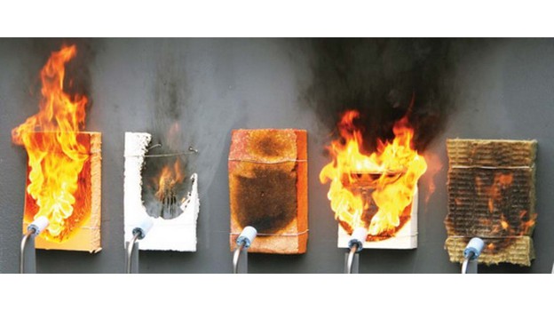
 Samples of materials are subjected to tests in laboratories and in open areas according to standard methods separately for non-combustible and combustible building materials.
If the products consist of several layers, the regulatory is provided for a flammability check for each layer.
Definitions are carried out on special equipment. If it turns out that one of the combustion components is high, this status will be enshrined in the product as a whole.
Installation for experimental definitions should be indoors with room temperature, normal humidity, without drafts. Bright sunny or artificial light in the laboratory should not interfere with reading testimony from displays.
 Before starting the sample study, the device is checked, calibrated, warmed. The sample is then fixed in the furnace's internal cavity holder and immediately include registrars.
The main thing is that no more than 5 seconds have passed since the sample placement. The definition continues to achieve the temperature balance, at which there are no more than 2 ° C for 10 minutes.
At the end of the procedure, the sample along with the holder is removed from the furnace, cooled in the desiccator, weighed and measured, ranging them to the combustibility group NG, G1 and so on.
All building materials, including finishing, facing, paintwork types of coatings, regardless of homogeneity or multi-layered, are examined by a combustibility in a single method.
 Pre-prepare 12 units of identical samples with a thickness equal to real values \u200b\u200bduring operation. If the structure is layered, take samples from each surface.
The samples are then kept at room temperature and normal ambient air humidity at least 72 hours, periodically weighing. Holding should be stopped when a constant mass is reached.
The installation has a standard design, consists of a combustion chamber, air supply systems and removal of released gases.

Samples in turn are placed in the chamber, measurements are carried out, fix the loss of mass, temperature and the number of gas-shaped gaseous products, burning time without a flame source.
Analyzing all the indicators obtained, determine the level of flammability of the material, belonging to a specific group.
 When erecting buildings, several different species Building materials: constructive, insulating, roofing, finishing with distinguished assignment and loads. All products should be available and presented to potential buyers certificates.
You should familiarize yourself with the parameters characterizing security, firmly know what can mean each reduction and numbers. The law requires only materials of the combustibility group G1 or NG for construction ceil frames.
Inflammability - the ability of substances and materials to ignition.
Federal Law No. 123-FZ dated July 22, 2008 "Technical Regulations on Fire Safety Requirements" determines the general requirements that determine the possibility of using construction and finishing materials Depending on their flammability indicator.
The flammability indicator is also taken into account when choosing materials for finishing floors, walls and ceilings on evacuation paths in buildings.
The essence of the method of determining the flammability of the material consists in determining the flammability parameters of the material at a given standard level of exposure to the surface of the test sample of the radiant heat flux and flame from the ignition source.
The flammability parameters of the material are the critical surface density of the heat flux (KPPTP) and the ignition time.
For the classification of materials by flame immigrants, KTPTP is used (the minimum value of the thermal flow density at which a stable flame burning occurs).
Flawing construction materials (according to GOST 30244) depending on the size of the KPTP (the minimum value of the surface density of the heat flux in which the steady flame burning occurs) is divided into three groups of flammability: B1, B2, B3.
For testing in the FSBI SEU FPS ILL in the Republic of Mordovia, it is necessary to provide 15 samples of square shape, with 165 mm sides and a deviation of minus 5 mm. The thickness of the samples should be not more than 70 mm. With each size of the surface density of the heat flux (PTPP), the tests are carried out on three samples.
In the manufacture of samples, the exhibited surface should not be processed.
If there is a corrugation, relief, embossing on the surface of corrugations, relief, embossing, etc. The size of the protrusions (vpadin) should be no more than 5 mm.
When the exhibited surface is discrepted to the specified requirements, it is allowed for testing samples from a flat surface material, i.e. Without corrugations, relief, embossing, etc.
Samples for standard testing of materials used only as finishing and facing, as well as to test paint coatings and roofing materials, are made in conjunction with a non-combustible basis. The method of fastening should ensure the tight contact of the surfaces of the material and the base.
As a non-combustible foundation should be used asbestos-cement lists According to GOST 18124, a thickness of 10 or 12 mm.
In cases where conditions for standard testing are not provided in specific technical documentation, the samples are made with the basis and fastening specified in the technical documentation.
For layered materials with different surface layers, two sets of samples are made to explorate both surfaces. In this case, the flammability group of the material is set for the worst result.
The testing of the samples is carried out in the thermal laboratory on the test installation "flammability".
Scheme of the definition of the flammability of materials. 1 - radiation panel with heating element; 2 - moving torch; 3 - auxiliary fixed burner; four - power cable heating element; 5 - Fist with a stroke limiter for manual control of the movable burner; 6 - cam for automatic control of the movable burner; 7 - drive belt; 8 - sleeve for connecting the moving torch to the fuel supply system; 9 - mounting plate for the ignition system and the moving burner movement system; 10 - protective cooker; 11 - vertical support; 12 - vertical guide; 13 - mobile platform for sample; 14 - base of the supporting bed; 15 - manual control; 16 - lever with a counterweight; 17 - drive to the electric motor.
Type of installation "Flammability"

Processing results are carried out according to the GOST 30402-96 technique. For each tested sample, the ignition time is recorded and the following additional observations: time and place of ignition; The process of destruction of the sample under the action of thermal radiation and flame; Melting, swelling, bundle, cracking, swelling or shrinkage.
After testing and paying the cost of the test, the employees of the test fire laboratory prepare the reporting documentation.
An important parameter of materials, especially in the field of construction, is their composure. It is so priority that the flammability groups define the federal law. Four them: g1-g4. A separate discharge is allocated. It is important to understand what this classification means, it will allow specialists to choose and use building materials to ensure fire safety of objects. It is possible to determine the degree of fire consumption only in a special laboratory having official profile accreditation. Methods regulates GOST 30244-94.
If the experimental way is established that the building material with ignition loses no more than 50% of the weight with ignition, the temperature grows - no more than +50 degrees, and the flame remains no more than 50 seconds, it is determined by its non-causing and it is considered fire-resistant. If one of the criteria does not correspond to the definition, the substance is fuel, and belongs to one of four groups:
Important! In the process of testing, the following process difference is taken into account: for the first two classes, the formation of molten droplets is not expected, for three groups - from G1 to G3 is not intended to form a burning melt.
In addition to flammability classes, flammability characteristics are of great importance. They are calculated by the values \u200b\u200bof the limiting density of thermal flows. Distinguish three categories:
In addition to flammability and flammability, the fire hazard of materials is established according to the smoke-forming ability (divided by D1-D3), the possibility of spreading the flame on the surface (RP1-RP4) and the degree of toxicity of combustion products (T1-T4).
For evidence, imagine the definition of fire safety classes in the table structure.
| Execution criteria | Km 0. | Km1 | Km2 | Km3 | Km4 | Km5 |
| Burning potential | NG | G1. | G1. | Г2. | Г2. | G4 |
| Ability to ignite | — | IN 1 | IN 1 | AT 2 | AT 2 | IN 3 |
| Smoke formation | — | D1 | DZ +. | D3. | D3. | D3. |
| The degree of toxicity of burning substances | — | T1. | T2. | T3. | T3. | T4. |
| Spreading fire | — | RP1 | RP1 | RP1 | RP2. | RP4 |

When choosing building materials for a particular building or construction, their fire safety class takes into account. Moreover, this criterion must match construction, finishing, insulating and roofing products. Decoding G1 indicates that the smelting material is the smallest - the first degree, that is, this is a fire-resistant product. All building materials must have compulsory certificates confirming the group of their fire resistance. This requirement is defined by SNiP and TNPA. So combustibility G1 indicates that the use of material in construction is relevant at objects with high fire safety requirements. That is, they can be used to build the designs of ceilings, roofing and frames of partitions to which the most stringent requirements are presented.
It should be understood. In kindergartens, schools and medical institutions, claims to fireproof may be higher - only NG. Similar requirements and towards evacuation paths on any objects.

According to Wikipedia, Mineral Materials are non-combustible. This is ceramics, a natural stone, reinforced concrete, glass, brick and analogues. But if the production uses additives with another nature, then the packaging parameters are changed. Modern technologies Expand the widespread use of polymer and organic additives. Depending on the proportions of combustible and non-combustible components in the composition, the parameters of the building material can be transformed to G1, and even to the gramifications class.
To determine the substances and products in classes of G4-G1 exist special techniques. They are checked for self-burning and ignition from the source, the ability to maintain the flame is taken into account. Tests are carried out in the chamber, such parameters are defined so experimentally:
After the seizures of samples from the chamber determine the intact part, that is, the percentage of total volume, which is not charred and has not burned. Results are rounded up to 1 centimeter. Such defects like charring, swelling, chip, roughness, color changes and the calculations are not accepted. The intact part is weighed on the scales, the accuracy of which should be at least 1%. All results obtained are entered into reporting documentation, including photo report. When determining the non-compliance of product characteristics to the safety requirements at the facility, a report is drawn up.
Fire experiments can only carry out those commercial organizations that have accreditation. Example: Research Institute of Kucherenko, Ministry of Emergency Situations, Anno "Fire Audit" and others. These enterprises are required to act purely on regulatory provisions, have a complete set of equipment that has passed the calibration and specialists of proper qualifications in the state. The protocol must contain the following information:

We give the parameters of fire resistance of popular construction products:
Note! Special requirements are presented to translucent designs. For them, detailed standards are drawn up with recommendations.
GOST 30402-96
Group Ж39
Interstate standard
Construction materials
Flare Test Method
BUILDING MATERIALS.
Ignitability Test Method.
OX 13.220.50
OKSTA 5207.
Date of introduction 1996-07-01
Preface
1. Developed by the State Central Research and Research and Experimental Institute of Comprehensive Problems building structures and structures named after V.A. Khercherenko (TsNIYSK NIKHENKO) of the State Scientific Center "Construction" (SSC "Construction") Ministry of Construction of Russia together with the All-Russian Research Institute of Fire Defense (VNIIPO) of the Ministry of Internal Affairs of Russia and the Center for Fire Research and Heat Protection in Construction TsNIIK (CPITZS TsNIIK)
Deposited by the Ministry of Internal Affairs of Russia
2. Adopted by the Interstate Scientific and Technical Commission on Standardization, Technical Registration and Certification in Construction (MNTKS) on May 15, 1996.
For the adoption voted
Name of state | Name of the authority of government construction |
The Republic of Azerbaijan | Gosstroy Azerbaijan Republic |
Republic of Armenia | State Spiritchitectures of the Republic of Armenia |
The Republic of Moldova | Minarkhstroy Republic of Moldova |
the Russian Federation | MinStroy Russia |
The Republic of Tajikistan | Gosstroy Republic Tajikistan |
The Republic of Uzbekistan | Goscomarchitektroy Republic Uzbekistan |
3. Entered for the first time
4. Entered into force from 01.07.96 as a state standard Russian Federation Resolution of the Ministry of Internal Affairs of Russia dated 24.06.96. N 18-40.
Introduction
This standard was developed on the basis of ISO 5657-86 standard "Fire tests - a reaction to fire - flammability of building structures." The standard used fundamental provisions to determine the ability to ignite the construction products while simultaneously exposed to a radiant heat flux and an open flame from the ignition source. Equipment for testing is identical equipment recommended in the ISO standard.
This standard establishes the method of testing building materials on flammability and classification by their flammability groups.
This standard is used for all homogeneous and layered combustible building materials.
This standard uses links to the following regulatory documents:
GOST 12.005-88 CSBT. General sanitary and hygienic requirements for the air of the working area;
GOST 12.1.019-79 SSBT. Electrical safety. General requirements and nomenclature of protection types;
GOST 18124-95 sheets asbestos-cement flat;
GOST 30244-94 Building materials. Methods of combustibility testing;
ST SEV 383-87 Fire safety in construction. Terms and Definitions.
This standard uses the terms and definitions of Art CEV 383, as well as the following terms with the corresponding definitions:
3.1. Inflammability - the ability of substances and materials to ignition.
3.2. Ignition is the beginning of fiery burning under the action of the ignition source, with a real standard test is characterized by steady flame burning.
3.3. The time of ignition is the time from the beginning of the test before the emergence of sustainable flame burning.
3.4. Sustainable flame burning - burning that continues to the next effect on the sample of the flame from the ignition source.
3.5. The surface density of the heat flux (PTTP) is a radiant thermal flow, which affects the sample surface unit.
3.6. The critical surface density of the heat flux (KPPTP) is the minimum value of the surface density of the heat flux at which a stable flame burning occurs.
3.7. Exhibited surface - the surface of the sample undergoes the effects of radiant heat flux and flame from the ignition source when tested on flammability.
4.1. The essence of the method consists in determining the flammability parameters of the material with the standard levels of exposure to the surface of the sample of the radiant heat flux and the flame from the ignition source.
The flammability parameters of the material are KPPTP and ignition time.
For the classification of materials in groups of flammability, KTPTP is used.
4.2. The density of the radiant heat flux must be from 10 to 50 kW / m.
4.3. The initial density of the radiant heat flux during tests (PTPT) is equal to 30 kW / m.
5.1. Flawing construction materials (according to GOST 30244), depending on the size of the PPPT, are divided into three groups of flammability: B1, B2, B3 (Table 1).
Table 1
Material flammability group | KTPTP, kW / m |
35 or more |
|
6.1. For tests, 15 samples having a square shape, with a side of 165 mm and a deviation of minus 5 mm. The thickness of the samples should be not more than 70 mm. At each value of the PTPP tests are carried out on three samples.
6.2. In the manufacture of samples, the exhibited surface should not be processed.
If there is a corrugation, relief, embossing on the surface of corrugations, relief, embossing, etc. The size of the protrusions (vpadin) should be no more than 5 mm.
When the exhibited surface is discrepted to the specified requirements, it is allowed for testing samples from a flat surface material, i.e. Without corrugations, relief, embossing, etc.
6.3. Samples for standard testing of materials used only as finishing and facing, as well as to test paint coatings and roofing materials, are made in conjunction with a non-combustible basis. The method of fastening should ensure the tight contact of the surfaces of the material and the base.
Asbestos-cement sheets according to GOST 18124 with a thickness of 10 or 12 mm should be used as a non-combustible basis.
In cases where conditions for standard testing are not provided in specific technical documentation, the samples are made with the basis and fastening specified in the technical documentation.
6.4. Paintwork coatings, as well as roofing mastics, should be based on at least four layers, while the consumption of material when applied to the base of each layer must comply with the technical documentation.
6.5. For materials used as independently (for example, for designs) and as finishing and facing, samples must be manufactured according to 6.1 (one set) and 6.3 (one set).
In this case, the tests are carried out separately for the material and separately using it as finishes and facing.
6.6. For layered materials with different surface layers, two sets of samples are made (according to 6.1) for the purpose of exposing both surfaces. In this case, the flammability group of the material is set for the worst result.
6.7. Before testing, the samples are conditioned until a constant mass at a temperature of 232 and a relative humidity of 505%. The constancy of the mass is considered achieved if with two consecutive weighing at an interval of 24 hours difference in the mass of the samples is not more than 0.1% of the initial mass of the sample.
7.1.1. The general type of installation for flammability tests is shown in Figure A1.
The installation consists of the following main parts:
Supporting bed;
Mobile platform;
The source of the radiant heat flux (radiation panel);
The ignition system (auxiliary stationary burner, a movable burner with a mechanized and manual displacement system).
7.1.2. Part auxiliary equipment Count: Sample holder, shielding plate, holder with imitator, flow control system gas-air mixtureregulating and registering devices, heat flux meter, time recorder.
7.1.3. The installation must be equipped with a protective screen and exhaust umbrella.
7.1.4. All sizes given in the following installation description, as well as figures, are nominal, except for those specified with tolerances.
7.2.1. The design of the supporting bed, the main components and parts of the moving platform movement system are presented in Figures A2 and A3.
7.2.2. The base of the basement is made in the form of a rectangular frame of 275 x 230 mm from the profile square cross section 25 x 25 mm with a wall thickness of 1.5 mm.
At the corners of the frame mounted four vertical supports with a diameter of 16 mm for fastening the protective plate. The distance from the frame to the protective plate is 260 mm.
7.2.3. The protective plate has a square shape with a side of 220 mm, a stove thickness of 4 mm. In the center of the protective plate, a hole with a diameter of 150 mm is cut. On the edge of the hole from the top side of the plate, the champions are cut at an angle of 45 with a size of 4 mm.
7.2.4. The mobile platform for the sample has the shape of a square with a side of 180 mm, the thickness of the platform is 4 mm. In the center of the lower side of the platform, a vertical rod with a grain at the lower end of the rod is installed. The diameter of the rod is 12 mm, length 148 mm.
7.2.5. The moving platform movement system consists of two vertical guides (rods at least 355 mm long and a diameter of 20 mm), a horizontal mobile strip (section 25 x 25 mm) with two sleeves at the ends of the plank and a hole in the center for the vertical rod of the mobile platform, as well as Lever with counterweight.
7.2.6. Vertical guides are mounted in the center of short sides of the frame (base of the basement).
The horizontal movable bar is installed on vertical guides. The bushings must provide free movement of the bar on the guides. The position of the bar is manually fixed using screws.
Under the horizontal bar, a lever with a counterweight is installed. The lever must end with a roller resting in a vertical rod of the mobile platform.
7.2.7. The counterweight lever should ensure the movement of the platform with the sample to the protective plate until the tight contact of the sample surface and the protective plate is reached. The specified requirements satisfies the lever with a length of about 320 mm with a counterweight mass of about 3 kg.
When melting, softening or shrinking the sample is allowed to displace the platform relative to the protective plate at a distance of no more than 5 mm. To perform this requirement, an adjustable stopper is installed or gaskets made of non-combustible material are used between the platform and the protective stove.
7.3.1. The radiation panel (Figures A4, A5) should provide the standard levels of exposure to the radiant heat flux in the center of the reservoir of the protective plate, in the plane coinciding with its lower surface.
7.3.2. The radiation panel is installed on vertical guide supporting beds. At the same time, the distance from the lower edge of the radiation panel to the upper plane of the protective plate should be 221 mm.
7.3.3. The radiation panel consists of a casing with a heat insulating layer and heating element. A non-combustible mineral fiber material is used as a heat insulating layer.
7.3.4. The heating element with a diameter of 8 to 10 mm and a length of about 3.5 m (the rated power of 3 kW) is folded in the form of a truncated cone and attached to the inner surface of the casing.
7.3.5. On the surface of the heating element, two thermoelectric converters are installed in two diametrically opposite points. Each of them is attached to the twist of the heating element at a distance from 1/3 to 1/2 height of the casing of the radiation panel from its upper edge.
The mounting method should provide dense contact of thermoelectric converters with the surface of the heating element. One of the recommended attachment methods is shown in Figure A5.
One of the thermoelectric converters is used to control the heater temperature (adjusting thermoelectric converter), the second to control the heater temperature (controlling the thermoelectric converter).
7.4.1. The movable burner should move from the original position over the radiation panel to the operating position inside the panel. The design of the mobile burner and the system of its movement is shown in Figures A6 - A8.
7.4.2. The auxiliary burner is intended for igniting the moving burner in the event of its attenuation. The diameter of the nozzle of the auxiliary burner is from 1 to 2 mm.
7.4.3. In the working position, the flame torch of the movable burner should be located above the center of the hole in the protective plate in the plane perpendicular to the direction of movement of the burner. At the same time, the center of the burner nozzle must be located at a distance of 101 mm from the plane of the movable plate.
7.4.4. The movable burner should move from the initial position to the working position every 4C. The time of finding the burner in the working position should be 1 s.
7.5.1. The sample holder is a flat metal sheet, on the upper surface of which there are samples for installation and fixation of the sample (Figure A9). On the lower surface of the holder, there are guides and a stopper that locks the position of the holder.
7.5.2. The shielding plate (Figure A10) is intended to protect the surface of the sample from the effects of heat flux. The shielding plate is made of leaf aluminum or stainless steel 2 mm thick.
7.5.3. A sample simulator is made of non-combustible mineral fiber material with a density of 20050 kg / m (Figure A11). The imitator sample holder is made of a non-combustible material with a density of 825125 kg / m.
7.5.4. The gas-air flow rate control system (Figure A12) connects to sources of gaseous fuel (propane or propane-butane mixture) and air, contains needle valves, flowmeters with the upper measurement limit of at least 1.2 l / h (for gas) and at least 12 L / h (for air) with an error of no more than 4%. It is also recommended on fuel and air lines. Place filters to protect flow meters from impurities.
7.5.5. The device that regulates the temperature of the heating element of the radiation panel must be calculated on the power of at least 3 kW and the current strength of at least 15 A. To register the temperature, it is recommended to use the device with a accuracy class of at least 0.5.
7.5.6. To measure the PTPP, it is recommended to use the device with a measurement range from 1 to 75 kW / m, measurement error - no more than 5%. To register the thermal stream meter testimony, a recorder with an accuracy class is not less than 0.1.
7.5.8. The placement location is equipped with protective screens and exhaust ventilation (Figure A13). In the exhaust umbrella, an airflow reflector is installed, providing air velocity from 2 to 3 m / s in the gaps at air flow from 0.25 to 0.35 m / s.
8.1.1. The goal of calibration is to establish the values \u200b\u200brequired by this standard for 4.2, as well as the uniformity of its distribution within the exhibited surface of the sample.
8.1.2. The uniform distribution of the heat flux on the exposed sample surface is ensured by following the following conditions:
- Deviation of PTPP in any four diametrically opposite points of the circle with a diameter of 50 mm from the value of the PTPP in the center of the exhibited surface should be no more than 3%;
- Deviation of PTPP in any four diametrically opposite points of the circle with a diameter of 100 mm from the value of the PTP in the center of the exhibited surface should be no more than 5%.
8.1.3. The establishment of the required PTP values \u200b\u200brequired by determining the dependence of the PTP in the center of the exposed surface on the temperature of the heating element.
8.1.4. Calibration is carried out on samples (3 pcs.) Having a square shape, with a side of 165 mm and a deviation of minus 5 mm. The thickness of the calibration sample should be at least 20 mm. For the manufacture of the calibration sample, asbestos-cement sheets according to GOST 18124 are used.
In the calibration samples, the hole is cut for the installation of the heat flux meter: in the first sample - in the center, in the second sample - at any point of the circle with a diameter of 50 mm, in the third sample - at any point of the circle with a diameter of 100 mm.
8.1.5. Calibration is carried out at metrological certification of the installation or replacement of the heating element and / or thermoelectric converters.
8.2.1. When calibrating, the movable burner should be in the initial position, the fuel and air supply system valves are blocked.
8.2.2. Install the heat flux meter into a calibration sample with a hole in the center of the exhibited surface.
8.2.3. Place the calibration sample in the holder and set to a movable platform.
8.2.4. Includes power supply and by changing the power supplied to the heating element of the radiation panel, are selected according to the regulatory thermoelectric converter the magnitude of the thermopower, in which the heat flux of 50 kW / m density is provided in the center of the exhibited surface.
8.2.5. Withstand the installation in the heating mode of 8.2.4 at least 10 minutes and fix the magnitude of the thermopower of the controlling thermoelectric converter.
8.2.6. Repeat operations of 8.2.4, 8.2.5 in order to determine the magnitudes of the thermoedues, providing in the center of the exhibited surface heat flows with a density of 45, 40, 35, 30, 25, 20, 10, 5 kW / m.
8.2.7. After performing operations to 8.2.6, the heat flux meter into a calibration sample with a hole on a circle with a diameter of 50 mm and repeat the operations of 8.2.3 - 8.2.5 for heat fluxes with a density of 50, 40, 30, 20, 10 kW / m.
These measurements are repeated for each of the four diametrically opposite points of the circle, changing the position of the sample in the holder.
8.2.8. Repeat the calibration procedure to 8.2.7 on the calibration sample with a hole on the circle with a diameter of 100 mm.
8.2.9. In case of inconsistency of the measurement results of the PTP with the requirements 8.1.2, replace the heating element of the radiation panel.
8.2.10. Calibration control of the installation is carried out every 60 hours of the radiation panel in the value of the PTPP equal to 30 kW / m, in the center of the exhibited surface.
Installation calibration is repeated if the deviation of the measured value of the PTP is more than 0.06 kW / m.
9.1. A sample for testing, conditioned in accordance with 6.7, wrapped with a sheet of aluminum foil (nominal thickness of 0.2 mm), in the center of which a hole with a diameter of 140 mm is cut. At the same time, the center of the hole in the foil should coincide with the center of the exposed sample surface (Figure A14).
9.2. The test sample is placed in the holder, it is installed on a movable platform and adjust the counterweight. After that, the holder with a test sample is replaced by a model with a simulator.
9.3. Install the moving burner at the starting position of 7.4.1, regulate the consumption of gas (19-20 ml / min) and air (160 - 180 ml / min) supplied to the movable burner. For the auxiliary burner, the flame flame length is approximately 15 mm.
9.4. Includes power and on the controlling thermoelectric converter, the magnitude of the thermopower is set when calibrated, corresponding to the PTP 30 kW / m.
9.5. After reaching the defined magnitude, the thermoem installation is maintained in this mode for at least 5 minutes. In this case, the magnitude of the thermoem, recorded according to the controlling thermoelectric transducer, should differ from the calibration obtained by no more than 1%.
9.6. Place the shielding plate on the protective plate, replace the sample-simulator to the test sample, include the mechanism of the movable burner, remove the shielding plate and include the time recorder.
The time of these operations should be no more than 15 seconds.
9.7. After 15 minutes or when the sample is ignited, the test is stopped. To do this, it is placed on the shielding plate on the protective plate, stop the time recorder and the mechanism of the movable burner, remove the holder with the sample and placed on the movable platform sample-simulator, remove the shielding plate.
9.8. Set the value of the PTP 20 kW / m, if there is an inflammation in the previous test, or 40 kW / m in its absence. Repeat operations of 9.5 - 9.7.
9.9. If, with PTPP 20 kW / m, ignition was recorded, reduce the value of the PTP to 10 kW / m and repeat the operations of 9.5 -9.7.
9.10. If there is no ignition with a 40 kW / m, there is no ignition, set the value of the PTP 50 kW / m and repeat the operations of 9.5 -9.7.
9.11. After determining the two values \u200b\u200bof the PPTP, with one of which there is a ignition, and during the other there is no, set the value of the PTP with 5 kW / m more than the magnitude in which there is no ignition, and repeat operations of 9.5 - 9.7 on three samples.
If the PTPP 10 kW / m recorded ignition, the following test is carried out at 5 kW / m PTPP.
9.12. Depending on the results of the tests of 9.11, the value of the PTPP increases by 5 kW / m (in the absence of ignition) or decrease by 5 kW / m (if there is ignition) and repeat operations of 9.5 - 9.7 on two samples.
9.13. For each tested sample, the ignition time is recorded and the following additional observations: time and place of ignition; The process of destruction of the sample under the action of thermal radiation and flame; Melting, swelling, bundle, cracking, swelling or shrinkage.
9.14. For materials with high compressibility (mineral wool plates), as well as materials melting or softening during heating, the test should be carried out with regard to 7.2.7.
9.15. For materials purchasing when heated, the ability to stick or form the surface charred layer with low mechanical strength, or under the surface-exposed air gap, in order to prevent interference with the movement of the movable burner or damage to the burner of the exhibited surface of the test sample should be carried out using a stopper in the drive mechanism, Eliminating the possibility of contacting the moving torch with the surface of the sample.
9.16. For materials forming a significant amount of smoke or decomposition products, the flames of the rolling torch and eliminate the possibility of re-ignition with the auxiliary burner, the result is fixed in the test protocol with an indication of the absence of ignition due to systematic deviation of the flame of the movable burner of decomposition.
The test reports in the test report:
Name of testing laboratory;
Name of the customer;
Name of the manufacturer (supplier);
Description of material or product, technical documentation, as well as trademark, composition, thickness, density, mass and method of manufacturing samples, characteristics of the exposed surface, for layered materials - the thickness of each layer and the characteristic of the material of each layer;
- flammability parameters: PTTP, ignition time with PTP for each of the samples;
- the conclusion about the material of the flammability of the material indicating the quantity of the CPTP;
- Additional observations when testing the sample: time and place of ignition; The process of destruction of the sample under the action of thermal radiation and flame; Melting, swelling, bundle, cracking, swelling or shrinkage.
The room in which tests must be equipped supply-exhaust ventilation. Workplace The operator must satisfy the requirements of electrical safety according to GOST 12.1.019 and sanitary and hygienic requirements according to GOST 12.1.005.
Appendix A.
(Reference)
Dimensions in millimeters
1 - radiation panel with heating element; 2 - moving torch;
3 - auxiliary fixed burner; 4 - power cable heating element;
5 - Fist with a stroke limiter for manual control of the movable burner; 6 - cam for automatic control of the movable burner; 7 - drive belt; 8 - sleeve for connecting the moving torch to the fuel supply system; 9 - mounting plate for the ignition system and the moving burner movement system; 10 - protective cooker;
11 - vertical support; 12 - vertical guide; 13 - mobile platform for sample; 14 - base of the supporting bed; 15 - manual control; 16 - lever with a counterweight;
17 - Drive to the electric motor
Figure A1 - general form Installations for flammability tests
Dimensions in millimeters
Figure A2 - Supporting Stanna (incision on BB)
Dimensions in millimeters
Figure A3 - Supporting Stanna (section of AA)
1 - radiation panel; 2 - protective cooker; 3 - mobile platform;
4 - counterweight; 5 - lever
Figure A4 - Supporting Stanne and Radiation Panel
Dimensions in millimeters
1 - casing with heat insulating layer; 2 - heat insulating layer of mineral fiber;
3 - heating element; 4 - clamp; 5 - thermoelectric converter
Figure A5 - Radiation Panel
Dimensions in millimeters
Detail 5 Detail 6
1 - sleeve for connecting the movable burner to the fuel supply system;
2 - flexible hose.; 3 - counterweight; 4 - roller; 5 - nozzle; 6 - Flame Stabilizer
Figure A6 - Mobile Burner
Dimensions in millimeters
1 - shaft of the drive mechanism; 2 - cam cutter;
3 - Fist with a stroke limiter; 4 - shaft of manual control;
5 - line passing through the center of the radiation panel
Figure A7 - Mounting plate of moving burner
1 - cam drive mechanism; 2 - Fist with a stroke limiter
Figure A8 - Mobile burner drive mechanism (mesh with a square of 10 mm)
Dimensions in millimeters
1 - rivets; 2 - handle; 3 - metal sheet (thickness 0.7)
Figure A9 - Sample holder
Dimensions in millimeters
1 - flat sheet of aluminum or stainless steel (thickness 2 mm);
2 - handle; 3 - Rivets
Figure A10 - shielding plate
Dimensions in millimeters
1 - plate of mineral fiber; 2 - an angular rack with a self-spinning screw;
3 - base sample simulator; 4 - Handle
Figure A11 - Sample-simulator
1 - temperature controller; 2 - Connect the thermocouple; 3 - Power supply;
4 - Millivoltmeter; 5 - heat flux meter; 6 - radiation panel; 7 - movable burner;
8 - auxiliary burner; 9 - sleeve for connecting the moving torch to the power system
fuel; 10 - non-refundable valves; 11 - needle valve; 12 - gearbox;
13 - flow meters; 14 - filters; 15 - needle valves; 16 - pressure regulators gearboxes;
17 - fit of compressed air; 18 - Propane
Figure A12 - Schematic scheme Installation and accessories
Dimensions in millimeters
1 - reflector; 2 - gap (for all edges of the reflector); 3 - Protective Screens
Figure A13 - Exhaust Umbrella and Protective Test Installation Screen
on flammability
Dimensions in millimeters
1 - aluminum foil; 2 - Sample
Figure A14 - Preparation of the sample to the test
The text of the document is drilled by:
official edition
MNTKS - M.: MinStroy Russia,
GUP CPP, 1996
A combustion group Materials are determined according to GOST 30244-94 "Building materials. Methods of combustibility test", which corresponds to the international standard ISO 1182-80 "Fire Tests - Building Materials - Non-Combastibility Test". Materials depending on the values \u200b\u200bof the combustibility parameters defined by this GOST, are divided into non-combustible (NG) and combustible (d).
Materials are referred to non-flammable With the following values \u200b\u200bof flammability:
Materials that do not satisfy at least one of the specified parameter values \u200b\u200bare combustible.
Combustible materials depending on the values \u200b\u200bof flammability parameters are divided into four combustibility groups in accordance with Table 1.
Table 1. Group of flammability materials.
Material flammability group Determined according to GOST 30402-96 "Construction materials. The method of inflammability test", which corresponds to the international ISO 5657-86 standard.
In this test, the surface of the sample is exposed to a radiant heat flux and the effects of a flame from the ignition source. At the same time, the surface density of the heat flux (PTPP) is measured, that is, the magnitude of the radiant heat flux acting on the unit surface area of \u200b\u200bthe sample. Ultimately, the critical surface density of the heat flux is determined - the minimum value of the surface density of the heat flux (PTTP), in which the stable fiery burning of the sample occurs after the influence of the flame.
Depending on the values \u200b\u200bof the PPTA, materials are divided into three flame groups indicated in Table 2.
Table 2. Material flammability groups.
To classify materials for smoke-forming The ability to use the value of the smoke formation coefficient, which is determined according to GOST 12.1.044.
The smoke-forming coefficient is an indicator characterizing the optical density of smoke formed during flame burning or thermo-oxidative destruction of a certain amount of solid (material) under special tests.
Depending on the value of the relative density of smoke, the materials are divided into three groups:
D1 - with a small smoke-forming ability - the smoke-forming coefficient up to 50 m² / kg inclusive;
D 2 - with a moderate smoke-forming ability - a smoke-forming coefficient from 50 to 500 m² / kg inclusive;
D3. - with high smoke-forming ability - smoke-forming coefficient over 500 m² / kg.
Toxicity group Products combustion materials are determined according to GOST 12.1.044. The combustion products of the material sample are sent to a special chamber, where the experimental animals are located (mice). Depending on the condition of experimental animals, after exposure to combustion products (including death), materials are divided into four groups:
T1. - little dangerous;
T2. - moderately dangerous;
T3. - highly dangerous;
T4. - Extremely dangerous.


