Alarm loops (inputs)
Depending on the type of connected detectors, when programming the configurations of the Signal-10 blocks ver.1.10 and higher; "Signal-20P" version 3.00 and higher; "Signal-20M" ver. 2.00 and higher; "S2000-4" ver.3.50 and higher inputs can be assigned one of the following types:
Type 1 - Firefighter smoke two-threshold
Fire smoke detectors or any other normally open detectors are included in the AL. The unit can supply power to the detectors via a loop.
Possible AL modes (states):
In general, when using smoke detectors powered by an alarm loop, the "Fire input re-request blocking" parameter should be disabled. When the detector is triggered, the control panel generates an information message "Sensor triggering" and resets the AL state: it resets (briefly disconnects) the AL power supply for 3 seconds. After a delay equal to the value of the "Input analysis delay after reset" parameter, the control panel starts evaluating the state of the loop. If the detector is triggered again within 55 seconds, the AL goes into the "Fire1" mode. If the detector does not re-act within 55 seconds, the AL returns to the "Armed" state. From the "Fire 1" mode, the AL can switch to the "Fire 2" mode in the cases described above.
The parameter "Blocking of re-request of fire. Input" is used if the detector is powered from a separate source. This scheme is usually used to connect detectors with high current consumption (linear, some types of flame detectors and CO). With the "Fire input re-request blocking" parameter enabled, when the detector is triggered, the control panel generates an information message "Sensor triggering" and immediately switches the AL to the "Attention" mode. From the "Attention" mode, the AL can switch to the "Fire 1" mode in the cases described above.
Type 2. Combined single-threshold fireman
Fire smoke (normally open) and heat (normally closed) detectors are included in the AL. Possible AL modes (states):
When the heat detector is triggered, the unit goes into the "Attention" mode. When a smoke detector is triggered, the unit generates an information message "Sensor triggering". When the parameter "Blocking of re-request of ammo" is disabled. input ”, the block re-requests the AL state (for more details, see type 1). In case of confirmation of the smoke detector actuation, the AL goes into the "Fire 1" mode, otherwise it returns to the "Armed" mode. From the "Fire 1" mode, the AL can switch to the "Fire 2" mode in the cases described above. When the parameter "Blocking of re-request of the fire. input ", the device immediately switches the AL to the" Attention "mode. From the "Attention" mode, the AL can switch to the "Fire 1" mode in the cases described above.
Type 3. Firefighter thermal two-threshold
Fire heat detectors or any other normally closed detectors are included in the AL. Possible AL modes (states):
Type 16 - Fireman manual.
Unaddressed manual (normally-closed and normally-open) fire detectors are included in the AL. Possible AL modes (states):
When manual fire detectors are triggered, the unit immediately generates the Fire2 event, according to which the S2000M remote control can send a command to control the fire automation systems.
For each loop, in addition to the type, you can configure such additional parameters as:
The maximum length of the signaling loops is limited only by the resistance of the wires (no more than 100 Ohm). The number of detectors included in one loop is calculated by the formula: N = Im / i, where: N is the number of detectors in the loop; Im - maximum load current: Im = 3 mA for AL types 1, 3, 16, Im = 1.2 mA for AL type 2; i - current consumed by the detector in standby mode, [mA]. The principles of connecting the detectors are described in more detail in the manual of the corresponding blocks.
The use of these detectors ensures their full electrical and information compatibility with the units in accordance with the requirements of GOST R 53325-2012.
Outputs
Each BOD has relay outputs. Using the relay outputs of the devices, you can control various executive devices, as well as transmit notifications to the monitoring station. The tactics of operation of any relay output can be programmed, as well as the activation linkage (from a specific input or from a group of inputs).
When organizing a fire alarm system, the following relay operation algorithms can be used:
Control panel "Signal-20M" in stand-alone mode
Signal-20M can be used to protect small objects (for example, small offices, private houses, shops, small warehouses, industrial premises etc.).
The buttons on the front panel of the instrument can be used to control the inputs and outputs. Access to the buttons is limited using PIN codes or Touch Memory keys (256 user passwords are supported). User authority (for each PIN-code or key) can be flexibly configured - to allow full control, or to allow only re-arming. Any user can control an arbitrary number of zones, for each zone the arming and disarming powers can also be configured individually. The control of outputs using the "Start" and "Stop" buttons is implemented in the same way. Manual control will be performed in accordance with the programs specified in the device configuration.
Twenty alarm loops of the Signal-20M device provide sufficient localization of the alarm notification at the mentioned objects when any fire detector in the loop is triggered.
The device has:

Block-modular PPKUP based on the "S2000M" console and BOD with conventional loops
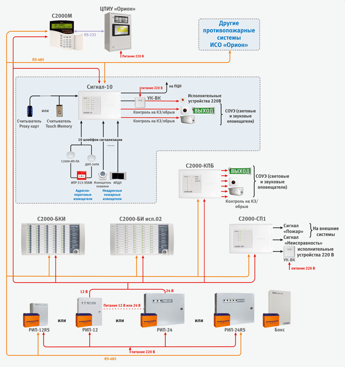
As mentioned above, when building a block-modular PPKUP, the S2000M console performs the functions of indicating the states and events of the system; organization of interaction between the components of the PPKUP (control of display units, expansion of the number of outputs, docking with the SPI); manual control of inputs and outputs of controlled units. It is possible to connect various types of threshold fire detectors to each of the BODs. The inputs of each of the devices are freely configurable, i.e. for any input types 1, 2, 3 and 16 can be set, and other configuration parameters can be assigned individually for each loop. Each device has relay outputs, with the help of which it is possible to control various executive devices (for example, light and sound annunciators), as well as transmit an alarm signal to the fire monitoring notification transmission system. For the same purposes, you can use control and start blocks "S2000-KPB" (with monitored outputs) and signal and start blocks "S2000-SP1" (with relay outputs). Additionally, the system is equipped with indication units "S2000-BI isp.02" and "S2000-BKI", which are designed to visually display the status of the inputs and outputs of devices and conveniently control them from the duty station.
Often, the S2000M console is also used to expand the fire alarm system during the reconstruction of the protected object to connect additional blocks for various purposes... That is, to increase system performance and build it up. Moreover, the build-up of the system occurs without its structural changes, but only by adding new devices to it.

The addressable threshold fire alarm in ISO "Orion" can be built on the basis of a block-modular PPKUP, consisting of:
Additionally, relay blocks "S2000-SP1" and "S2000-KPB" can be used to expand the number of system outputs; indication and control units "S2000-BI isp.02" and "S2000-BKI" for visual display of the status of inputs and outputs of devices and convenient control of them from the duty station.
When connecting the indicated detectors to the Signal-10 block, the device loops must be assigned type 14 - "Addressable-threshold fire". Up to 10 addressable detectors can be connected to one address-threshold loop, each of which is capable of reporting its current state at the request of the device. The device periodically polls addressable detectors, ensuring control of their performance and identification of a faulty or triggered detector.
Each addressable detector is considered as an additional virtual input of the BOD. Each virtual input can be disarmed and armed with a command from the network controller (“S2000M” console). When arming or disarming a threshold-addressable loop, the addressable detectors (virtual inputs) that belong to the loop are automatically removed or taken.
An addressable threshold loop can be in the following states (states are listed in order of priority):
When organizing an address-threshold security alarm system for the operation of outputs, you can use tactics similar to those used in a conventional system.
In fig. an example of the organization of an address-threshold fire alarm system using the "Signal-10" block is given.
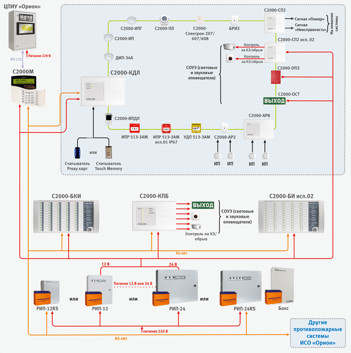
The analogue addressable fire alarm system in ISO "Orion" is built on the basis of a block-modular PPKUP, consisting of:
When organizing the address analog system For fire alarm systems, the S2000-SP2 and S2000-SP2 isp.02 devices can be used as relay modules. These are addressable relay modules, which are also connected to the "S2000-KDL" via a two-wire communication line. "S2000-SP2" has two relays of the "dry contact" type, and "S2000-SP2 isp.02" - two relays with monitoring the serviceability of the circuits for connecting executive devices (separately for OPEN and SHORT CIRCUIT). For the S2000-SP2 relay, you can use tactics of work similar to those used in the conventional system.
The system also includes sounders security and fire sound addressable "S2000-OPZ" and illuminated table addressable sirens "S2000-OST". They are connected directly to the DPLS without additional relay blocks, but require a separate 12 - 24 V power supply.
The S2000R-APP32 radio expander allows you to control the S2000R-Sirena light and sound radio channel siren. To control another fire load via the radio channel, the S2000R-SP unit is used, which has two controlled outputs.
Additionally, relay blocks "S2000-SP1" and "S2000-KPB" can be used to expand the number of system outputs; indication and control units "S2000-BI" and "S2000-BKI" for visual display of the state of inputs and outputs of devices and convenient control of them from the duty station.
The two-wire controller actually has two alarm loops to which a total of 127 addressable devices can be connected. These two stubs can be combined to form a DPS ring structure. Addressable devices are fire detectors, addressable expanders or relay modules. Each addressable device occupies one address in the controller memory.
Addressable expanders occupy as many addresses in the controller's memory as there are loops that can be connected to them ("S2000-AP1" - 1 address, "S2000-AP2" - 2 addresses, "S2000-AP8" - 8 addresses). Addressable relay modules also occupy 2 addresses in the controller memory. Thus, the number of protected rooms is determined by the address capacity of the controller. For example, with one "S2000-KDL" you can use 127 smoke detectors or 87 smoke detectors and 20 addressable relay modules. When the addressable detectors are triggered or when the loops of the addressable expanders are violated, the controller issues an alarm message via the RS-485 interface to the S2000M control panel. Controller "S2000-KDL-2I" functionally repeats "S2000-KDL", but has an important advantage - a galvanic barrier between the DPLS terminals and power supply terminals, RS-485 interface and reader. This galvanic isolation will increase the reliability and stability of the system at objects with a complex electromagnetic environment. It also helps to exclude the flow of equalizing currents (for example, in case of installation errors), the effect of electromagnetic interference or interference from the equipment used at the facility, or in the event of external influences of a natural nature (lightning discharges, etc.).
An input type must be specified for each addressable device in the controller. The input type indicates to the controller the tactics of the zone operation and the class of detectors included in the zone.
Type 2 - "Combined firefighter"
This type of input is intended for address expanders "S2000-AR2", "S2000-AR8" and "S2000-BRShS-Ex" (see section "Explosion-proof solutions ..."), in which the controller will recognize such states of the CC as "Norm" , "Fire", "Open" and "Short circuit". For "S2000-BRShS-Ex", the "Attention" state can be additionally recognized.
Possible input states:
Type 3 - "Firefighter thermal"
This type of input can be assigned to "S2000-IP" (and its modifications), "S2000R-IP" operating in differential mode, for "S2000-AP1" various designs controlling conventional fire detectors with a "dry contact" type output, as well as addressable detectors "S2000-PL", "S2000-Spectron" and "S2000-IPDL" and all modifications. Possible input states:
Type 8 - "Analog addressable smoke"
This type of input can be assigned to "DIP-34A" (and its modifications), "S2000R-DIP". The controller in the standby mode of the DPLS operation requests numerical values corresponding to the level of smoke concentration measured by the detector. For each input, the thresholds of the preliminary warning "Attention" and the warning "Fire" are set. Alarm thresholds are set separately for the "NIGHT" and "DAY" time zones. The controller periodically requests the value of the dustiness of the smoke chamber, the obtained value is compared with the “Dusty” threshold, set separately for each input. Possible input states:
Type 9 - "Thermal analog addressable"
This type of input can be assigned to "S2000-IP" (and its modifications), "S2000R-IP". The controller in the standby mode of the DPLS operation requests numerical values corresponding to the temperature measured by the detector. For each input, the temperature thresholds of the preliminary warning "Attention" and the warning "Fire" are set. Possible input states:
Type 16 - "Fireman manual"
This type of input can be assigned to "IPR 513-3A" (and its versions); "S2000R-IPR"; AL of address expanders. Possible input states:
Type 18 - "Fireman Launcher"
This type of input can be assigned to address "UDP-513-3AM" and their versions; AL of address expanders with connected UDP. Possible input states:
Type 19 - "Firefighter gas"
This type of input can be assigned to "S2000-IPG". The controller in the standby mode of the DPLS operation requests numerical values corresponding to the content of carbon monoxide in the atmosphere measured by the detector. For each input, the thresholds of the preliminary warning "Attention" and the warning "Fire" are set. Possible input states:
Additional parameters can also be configured for fire inputs:
The S2000-KDL controller also has a circuit for connecting readers. It is possible to connect a variety of readers using the Touch Memory or Wiegand interface. The readers can control the state of the controller inputs. In addition, the device has functional indicators of the operating mode status, DPS lines and an indicator of exchange via the RS-485 interface. In fig. an example of the organization of an analogue addressable fire alarm system is given.
As mentioned above, the radio channel extension of the analogue addressable fire alarm system, built on the basis of the S2000-KDL controller, is used for those premises of the facility where the laying of wire lines for one reason or another is impossible. The "S2000R-APP32" radio expander provides constant control of the availability of communication with 32 "S2000R" series radio devices connected to it and monitoring of the state of their power supplies. Radio channel devices carry out automatic control of the radio channel operability, and in case of its high noise level, they automatically switch to the backup communication channel.
Operating frequency ranges of the radio channel system: 868.0-868.2 MHz, 868.7-869.2 MHz. The radiated power in the transmission mode does not exceed 10 mW.
The maximum range of radio communication in open areas is about 300 m (the range of operation when installing a radio system in rooms depends on the number and material of walls and ceilings in the path of the radio signal).
The system uses 4 RF channels. At the same time, up to 3 "S2000R-APP32" can operate on each channel in the radio visibility zone. "S2000R-APP32" connects directly to the DPLS controller "S2000-KDL" and occupies one address in it. Moreover, each radio device will also occupy one or two addresses in the S2000-KDL address space, depending on the selected operating mode.
Algorithms of operation of radio devices are described above in the section dedicated to the types of inputs "S2000-KDL".

If necessary, fire alarm equipment for an object with explosive zones, together with an analogue addressable system based on the S2000-KDL controller, it is possible to use a line of specialized addressable explosion-proof detectors.
Multi-range flame detectors (IR / UV) "S2000-Spectron-607-Exd -..." (with special protection against false alarms for electric arc welding); thermal "S2000-Spectron-101-Exd -...", manual and UDP "S2000-Spectron-512-Exd- ...", "S2000-Spectron-535-Exd- ..." are manufactured in accordance with the requirements for explosion-proof equipment of the group I and subgroups IIА, IIВ, IIС according to TR CU 012/2011, GOST 30852.0 (IEC 60079-0), GOST 30852.1 (IEC 60079-1) and correspond to explosion protection marking PB ExdI / 1ExdIICT5. The explosion protection of these detectors is ensured by the sheath. Thus, the DPLS line in the hazardous area must be made with an armored cable. The DPLS is connected to the detectors through special cable glands. Their type is determined when ordering, depending on the method of cable protection.
The enclosure of the detectors marked - Exd-H is made of stainless steel. They are recommended to be installed in facilities with chemically aggressive media (for example, in the petrochemical industry).
For manual call points "S2000-Spectron-512-Exd- ..." the -B marking shows the possibility of additional sealing of the detector with seals, and -A the absence of such a possibility.
According to the standards, the detectors and UDP "S2000-Spectron-512-Exd- ..." and "S2000-Spectron-535-Exd- ..." can be used in the same way. Moreover, they have the same explosion protection marking and the same degree of protection of the inner volume by the enclosure. At the same time, the detectors and UDP “S2000-Spectron-535-Exd-…” provide the maximum speed of issuing “Fire” signals (or a control signal in the case of UDP). But they should not be used on facilities where there is a possibility of unauthorized (accidental) activation of the device. The detectors and UDP "S2000-Spectron-512-Exd- ..." have maximum protection against abnormal operations (including due to the presence of a seal). But because of this, the speed of issuing an alarming (control - in the case of UDP) signal to the system is somewhat reduced. They also have unique applications (for example, in metal ore mines where magnetic anomalies are possible) due to the optoelectric principle of operation. In addition, the products "S2000-Spectron-512-Exd- ..." are somewhat more expensive.
For the operation of flame detectors in the area low temperatures(below - 40oС) a thermostat is built inside - a device that, with the help of heating elements, in automatic mode, is able to maintain the operating temperature inside the case. The thermostat needs a supply additional source nutrition. The heating turns on at a temperature of -20oС.
Multi-range flame detectors (IR / UV) "S2000-Spectron-607-Exi" (with special protection against false alarms for electric arc welding) and multi-range flame detectors (IR / UV) "S2000-Spectron-608-Exi" have an explosion protection level "especially explosion-proof »With OExiaIICT4 X marking in accordance with TR CU 012/2011, GOST 30852.0 (IEC 60079-0), GOST 30852.10 (IEC 60079-11). The explosion protection of these detectors is ensured by an “ia” spark-proof circuit and an antistatic sheath. The connection to the DPLS is carried out with an ordinary cable through the "S2000-Spectron-IB" spark-proof barrier, installed outside the hazardous area.
These detectors are recommended to be installed at petrol stations, gas and oil refineries, painting booths. An explosion-proof multi-band (IR / UV) radio channel flame detector "S2000R-Spectron-609-Exd", connected to the expander "S2000R-APP32", has been developed for explosive zones.
Addressable explosion-proof detectors operate according to the "Heat Fire" tactics. The algorithm of their work is described above in the section devoted to the types of inputs "S2000-KDL".
Intrinsically safe barriers "S2000-BRShS-Ex" are used to connect other types of explosion-proof detectors. This unit provides protection at the level of an intrinsically safe electrical circuit. This method of protection is based on the principle of limiting the maximum energy stored or released by the electrical circuit in emergency mode, or dissipating power to a level significantly below the minimum energy or ignition temperature. That is, the voltage and current values that can enter the hazardous area in the event of a malfunction are limited. The intrinsic safety of the unit is ensured by galvanic isolation and the appropriate selection of the values of the electrical clearances and creepage distances between the intrinsically safe and associated spark-proof circuits, limiting the voltage and current to intrinsically safe values in the output circuits due to the use of intrinsically safe barriers filled with compound on zener diodes and current-limiting devices, providing electrical gaps, leakage paths and intactness of spark protection elements, including by sealing (filling) them with a compound.
"S2000-BRShS-Ex" provides:
The X sign after the explosion protection marking means that only explosion-proof electrical equipment with the type of services for environmental, technological and nuclear supervision in hazardous areas. "S2000-BRShS-Ex" occupies three addresses in the address space of the "S2000-KDL" controller.
It is possible to connect any threshold fire detectors to "S2000-BRShS-Ex". To date, CJSC NVP "Bolid" supplies a number of sensors for installation inside an explosive zone (explosion-proof design):
The S2000-BRShS-Ex inputs operate according to the Combined Firefighter tactics. The algorithm of their work is described above in the section devoted to the types of inputs "S2000-KDL".

When building distributed or large systems fire protection, in which more than one "S2000M" console is used, it becomes necessary to combine local subsystems at the upper level. For this purpose, the central display and control panel of the Orion CPIU, certified in accordance with GOST R 53325-2012, is intended. It is built on the basis of an industrial PC with a redundant power supply with a special full-featured version of the Orion Pro workstation installed on it and allows you to create a unified workstation for indicating and controlling fire systems for individual houses in residential areas, factories, and multifunctional complexes.
TsPIU "Orion" is installed in a room with a round-the-clock stay of the personnel on duty, into which information from individual consoles "S2000M" is collected via a local network. That is, the CPIU can simultaneously poll several subsystems, each of which is a PPKUP under the control of the S20000M console and organize network interaction between them.
TsPIU "Orion" allows you to implement the following functions:
Thus, software, used in the Orion CPIU, expands the functionality of the S2000M consoles, namely: organizes interaction (cross connections) between several consoles, maintains a general log of events and alarms of almost unlimited volume, allows indicating the causes of alarms and logging organizational actions of operators (calling the fire department security, etc.), collect statistics on the ADC of analogue addressable detectors (dustiness, temperature, gas content) and intelligent power supplies with information interfaces.
Traditionally, it is technically possible to connect the S2000M consoles to a PC with the Orion Pro workstation installed. In this case, due to the lack of certification of the PC according to fire standards, the AWP will not be part of the control panel or control device. It can be used only as an additional dispatching tool (for redundant visualization, logging of events, alarms, reporting, etc.), without management functions and networking between several consoles.
The assignment of automatic fire alarm tasks to software modules is shown in Fig. 9. It is worth noting that the devices are physically connected to the system computer on which the Orion Pro operational task software module is installed. The connection diagram of the devices is shown in the block diagram of the ISO "Orion". The block diagram also shows the number of workplaces that can be simultaneously used in the system (AWP software modules). Software modules can be installed on computers in any way - each module on a separate computer, a combination of any modules on a computer, or installation of all modules on one computer.

TsPIU "Orion" can be used in stand-alone mode or as part of the existing AWS "Orion Pro". In the first case, the CPU will include the following modules: Server, Operational Task, Database Administrator and Report Generator. In the second of all CPIU modules, it is enough to use the Operational task, which will be connected via the local network to a PC with an existing Server. In this case, the CPU will fully retain its functionality in the event of a loss of connection or failure of the PC with the Server.
All devices designed for fire alarm in ISO "Orion" are powered from low-voltage power supplies (IE) direct current... Most of the devices are adapted to a wide range of power supply voltages - from 10.2 to 28.4 V, which allows the use of sources with a nominal output voltage of 12 V, or 24 V (Fig. 3-7). A special place in the fire alarm system can be occupied by a personal computer with a dispatcher's workstation. It, as a rule, is powered from the AC mains, stabilization and redundancy of which is provided by uninterruptible power supplies, UPS.
Distributed placement of equipment over a large object, which is easily implemented in ISO "Orion", requires the provision of power to the devices in the places where they are installed. Given the wide range of supply voltages, it is possible, if necessary, to place power supplies with an output voltage of 24V at a distance from consumer devices, even taking into account a significant voltage drop across the wires.
There are other power supply schemes in analogue addressable fire alarm systems based on the S2000-KDL controller. In this case, addressable detectors and relay modules S2000-SP2 connected to the signal two-wire communication line of the S2000-KDL controller will receive power through this line. With such a power supply scheme, the controller itself and the S2000-SP2 isp.02 and S2000-BRShS-Ex units will be powered from the power supply.
If we consider the case of radio expansion of an analogue address system, then in accordance with clause 4.2.1.9 of GOST R 53325-2012, all radio devices have a main and backup autonomous power sources. At the same time, the average operating time of radio devices from the main source is 5 years and from the backup source - 2 months. "S2000-APP32" can be powered both from an external source (9 -28 V) and from a DPLS, but due to the high current consumption of the device, in most cases it is recommended to use the first power supply circuit.
The main regulatory document that defines the parameters of IE for fire alarm -. In particular:
1) IE should have an indication:
Availability (within normal limits) of main and backup or backup power supplies (separately for each power supply input);
The presence of an output voltage.
2) IE must provide the formation and transmission of information to external circuits of information about the absence of output voltage, input voltage of power supply at any input, battery discharge (if any) and other faults monitored by the IE.
3) IE must have automatic protection against short circuits and an increase in the output current above the maximum value specified in the TD on the IE. In this case, the IE should automatically restore its parameters after these situations.
4) Depending on the size of the object, power supply of the fire alarm system may require from one IE to several dozen power sources.
To power fire alarm systems, there is a wide range of certified power supplies with an output voltage of 12 or 24 V, with a load current from 1 to 10A: RIP-12 isp 06 (RIP-12-6 / 80M3-R), RIP-12 isp .12 (RIP-12-2 / 7M1-R), RIP-12 isp.14 (RIP-12-2 / 7P2-R), RIP-12 isp.15 (RIP-12-3 / 17M1-R), RIP-12 isp.16 (RIP-12-3 / 17P1-R), RIP-12 isp.17 (RIP-12-8 / 17M1-R), RIP-12 isp.20 (RIP-12-1 / 7M2 -R), RIP-24 isp 06 (RIP-24-4 / 40M3-R), RIP-24 isp 11 (RIP-24-3 / 7M4-R), RIP-24 isp 12 (RIP-24 -1 / 7M4-R), RIP-24 isp.15 (RIP-24-3 / 7M4-R)
These RIPs, designed to power the technical means of fire automation, have information outputs: three separate relays, galvanically isolated from the rest of the circuits and from each other. RIP monitors not only the presence or absence of input and output voltages, but also their deviations from the norm. Galvanic isolation of information outputs greatly simplifies their connection to any type of fire alarm and automation devices.
All devices and devices that are part of the fire alarm belong to electrical receivers of the first category of power supply reliability. This means that when installing a fire alarm system, it is necessary to implement an uninterruptible power supply system. If the facility has two independent high-voltage power supplies, or the ability to use a diesel generator, it is possible to develop and apply an automatic transfer switch (ATS) scheme. In the absence of such a possibility, the uninterruptible power supply is forcedly compensated by a redundant power supply using sources with a built-in or external low-voltage battery. In accordance with SP 513130-2009, the battery capacity is selected based on the calculated consumption current of all (or a group) of fire alarm devices, taking into account their operation on backup power in standby mode for 24 hours plus 1 hour of operation in alarm mode. Also, when calculating the minimum battery capacity, it is necessary to take into account the operating temperature, discharge characteristics, service life in the buffer mode.
To increase the operating time of the RIP in standby mode, additional batteries can be connected to RIP-12 isp.15, RIP-12 isp.16, RIP-12 isp.17, RIP-24 isp.11, RIP-24 isp.15 .) with a capacity of 17A * h installed in Box-12 isp.01 (Box-12 / 34M5-R) for RIP with an output voltage of 12V and Box 24 isp.01 (Box-24 / 17M5-R) for RIP with an output voltage of 24V ... These devices are presented in a metal case. These microprocessor-controlled products have overcurrent, polarity reversal and overdischarge protection elements. Information transmission to the RIP about the state of each of the AB installed in the BOX is carried out using a two-wire interface. All cables for connecting the Box to the RIP are included in their delivery set.
At facilities where special requirements are imposed on the reliability of the fire alarm system, power supplies with a built-in RS-485 interface can be used: RIP-12 version 50 (RIP-12-3 / 17M1-R-RS), RIP-12 version 51 ( RIP-12-3 / 17P1-P-RS), RIP-12 isp.54 (RIP-12-2 / 7P2-R-RS), RIP-12 isp 56 (RIP-12-6 / 80M3-P- RS), RIP-12 isp.60 (RIP-12-3 / 17M1-R-Modbus), RIP-12 isp.61 (RIP-12-3 / 17P1-R-Modbus), RIP-24 isp.50 ( RIP-24-2 / 7M4-R-RS), RIP-24 isp.51 (RIP-24-2 / 7P1-P-RS), RIP-24 isp 56 (RIP-24-4 / 40M3-P- RS), RIP-48 isp.01 (RIP-48-4 / 17M3-R-RS), which in the process of operation continuously measure the voltage in the network, voltage on the battery, output voltage and output current, measure the battery capacity and transmit the measured values (on request) to the S2000M console or the Orion Pro workstation. In addition, these sources provide temperature compensation for the battery charge voltage, thereby extending the battery life. When using these power supplies, using the RS-485 interface, on the S2000M console or computer with the Orion Pro workstation, you can receive messages: "Mains failure" (mains voltage below 150 V or above 250 V), "Power supply overload" ( RIP output current is more than 3.5 A), "Charger malfunction" (the charger does not provide voltage and current for charging the battery (AB) within the specified limits), "Power supply malfunction" (with an output voltage below 10 V or above 14.5 V ), "Battery malfunction" (voltage (AB) is below the norm, or its internal resistance is higher than the maximum allowable), "Burglary alarm" (RIP case is open), "Output voltage shutdown". RIPs have light indication and sound signaling of events.
In the absence of surge protection devices (SPD) in the facility's power supply circuit, as well as an additional level of protection, it is recommended to install protective network blocks BZS or BZS isp.01, placing them directly near the network inputs of redundant power supplies or other equipment powered directly from AC 220V. At the same time, for automatic restoration of the system operability, BZS isp.01 are used.
To distribute the load current, suppress mutual interference between several consumer devices and protect against overloads for each of the 8 channels, it is recommended to use protective switching blocks BZK isp.01 and BZK isp.02.
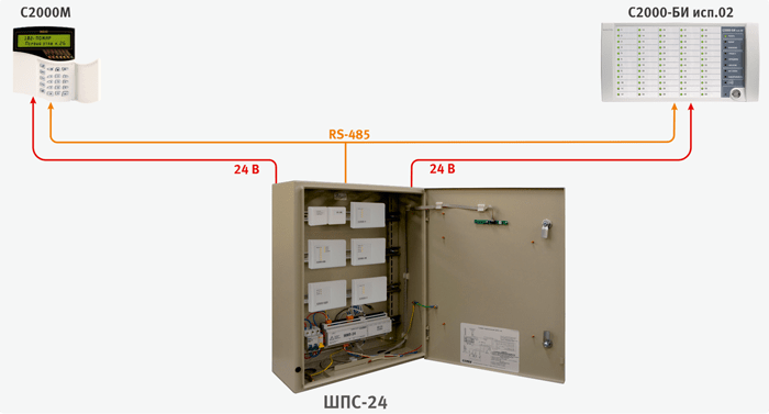
For compact placement of fire alarm and automation devices at the facility, cabinets with redundant power sources can be used: ShPS-12, ShPS-12 isp.01, ShPS-12 isp.02, ShPS-24, ShPS-24 isp.01, ShPS-24 isp.02.
These devices represent a metal cabinet in which ISO Orion devices can be installed: Signal-10, Signal-20P, S2000-4, S2000-KDL, S2000-KPB, S2000- SP1 "," S2000-PI "and others that can be mounted on a DIN rail. The devices can also be installed on the front door using the additional DIN rails included in the MK1 mounting kit. ~ 220 V circuits are protected by circuit breakers. Two 12 V batteries with a capacity of 17 A * h are installed in the cabinet.
Inside the cabinet are installed:
ShPS-12 isp.01 / ShPS-24 isp.01 are equipped with a window through which it is possible to visually inspect the devices installed inside. ShPS-12 isp.02 / ShPS-24 isp.02 have the degree of protection of the case IP54.
Solution of the problem fire safety any object, regardless of the form of ownership and purpose, without fail requires equipment with a fire or fire and security alarm system, with the function of detecting a fire source, alerting personnel and services of the Ministry of Emergency Situations. Even for the smallest facility where it is planned to install such equipment, it is imperative to draw up a fire alarm project that would meet all the rules and requirements, and this will only be the first step towards solving the problem of fire protection.
Independent development of a fire alarm and system project automatic fire extinguishing, like the development of any other project, must comply with the norms of existing rules and requirements in force at the time of project development. The main stages of work in the development of the document are:
The requirements for the document being developed are established by laws and government regulations governing the development procedure, content and main sections of the project fire alarm project. The main regulation here is the law of the Russian Federation No. 123-FZ dated July 22, 2008, it sets out the basic requirements for fire safety at facilities, including the features of maintenance and operation.
The classification of buildings and structures according to the degree of fire hazard is determined by the Government Decree No. 390 of 04/25/2012, based on this classification, and equipment for the alarm and fire extinguishing system is selected.
The issues of direct design, mandatory sections and the procedure for designing a project are disclosed in the Decree of the Government of the Russian Federation No. 87 of February 16, 2008.
Additional information required for the development of the project may be contained in the standards, state building codes and regulations, as well as in the orders of the Ministry of Emergency Situations of the Russian Federation.

The preparation of the technical assignment provides for the selection and analysis of information both about the facility where the equipment is planned to be installed, and the requirements put forward by the customer for the equipment, technical specifications and the principles of the system.
In the terms of reference for the development of a project of a fire safety system, the customer specifies:
In addition, for design, it is important to understand with which fire extinguishing systems the alarm will be activated, which of additional equipment will be proposed for installation as a comprehensive solution to the problem of fire safety.
A separate item of the terms of reference for the development of the project will be the issue of equipment power supply.
When drawing up a technical assignment, you must also indicate:

The beginning of the development of the project is the study of the technical task and the collection of the necessary information for drawing up the project.
It is mandatory to conduct a survey of the building, drawing up a primary plan for placing the elements of the system. Based on the information collected, a decision is made to develop a project with optimal technical solutions for installing special equipment.
In the development of the project can be used typical schemes installation of equipment blocks, wiring diagrams and placement of detectors used in other similar projects.
In the explanatory note to the project, information is indicated that must correspond to reality and reflect the real state of the object. In view of this, the description of the object indicates technical specifications buildings, its number of storeys, floor material, load-bearing walls and internal partitions. A separate moment there is a description of the intended purpose of the building - a residential building, commercial premises or an industrial building.
In the project, it is important to indicate the state of the building, its compliance with the fire safety requirements for this category of objects, the availability of evacuation means, smoke removal, emergency exits, fire hydrants, and an internal fire water supply system are indicated in the graphic part.
For rooms equipped with a centralized ventilation and air conditioning system, all ventilation ducts and air ducts of air conditioners are indicated.
In addition, for all premises, it is important to indicate the location of stationary equipment and furniture, and also indicate the evacuation routes for personnel and the most significant material values.
Particularly significant information in the project is information about engineering systems buildings - water supply system, heating, power supply, laid cable communication lines. When developing working drawings for a project, this information will have one of the most important roles. In addition, if there is already installed system signaling, it is necessary to study the possibility of using it as a backup system, or as auxiliary elements of individual blocks and nodes.
All the data obtained in the process of studying the primary information form the basis of the sketch plan, on the basis of which the development of all parts of the project will be carried out.
At the stage of developing a draft plan, the configuration of the future system is being developed, the compatibility of the main parts and elements, the locations of sensors, connecting lines, control units, sound detectors and signal boards are indicated. The calculation of the coverage areas of each sensor is carried out in accordance with its technical characteristics.
Based on the outline plan, the textual part of the project is being developed with a description of all of its component parts and a graphic plan by linking to the building plan of all design solutions.
In addition to the description and graphic part, the project also includes working documentation, which will be directly used for installation work. V working documentation may include both general plans and layouts, as well as detailed drawings of attachment points, options for placing typical elements, wiring diagrams for electrical equipment and algorithms for the operation of individual elements.
The fourth component of the project is the estimate of installation work and the calculation of the cost of equipment, including indicating the possibility of replacing individual elements with other models and modifications.
Working draft security and fire alarm store
Dwg format
Detection of unauthorized entry into the protected premises and issuance of "Intrusion" signals to the guard post;
Issuance of "Penetration" signals;
Arming and disarming individual loops (premises);


The reception and control device "Granit - 3" was used as a control and monitoring device for the OPS system.
Panic radio button "RR-2T", part of the radio-channel security alarm "Rif Ring - 2". Transmits alarm notifications via radio channel by switching relay contacts to the receiver "RR-2R".
The device "Granit-3" allows you to take under the protection of separate premises of the store: a trading floor, utility room, warehouse. Protection by the "Granit - 3" device is carried out by monitoring the state of the state of three loops of the security and fire alarm systems. Remote light-sound annunciators "Mayak-12K", light indicators of an exit and sound annunciator "Mayak - 12 - 3m" are connected to PPK "Granit - 3".
Power supply "Granit - 3" is carried out from the AC 220V and from the built-in backup battery with a capacity of 2.2 A / h.
Organization of protection of the premises of the OPS.
1. The trading floor is protected by three lines of the fire and security alarm system:
The 1st line notifies about the breaking of doors, this loop includes magnetic contact sensors "IO 102 - 26";
2nd line controls window openings, combined sensors "Astra - 8" are included in the loop;
3rd line - fire alarm, this line includes sensors "IPR 513-10" and "IP212-141".
2.The boiler room is protected by one fire alarm line:
The 1st line is represented by a loop of "IP 101 -1A-A1" heating sensors and "IPR 513-10" sensors.
3. In the utility room:
1st loop - control of doorways (sensors "Astra - 8");
2nd loop - smoke detectors "IP 212 - 141";
All loops are connected to the Granit-3 device installed in the sales area. Power supply to the redundant power supply units should be provided from separate 1P 16A machines installed in the AC power switchboard with a voltage of ~ 220V. Lay the ~ 220V power cables separately from low-current networks.
The fire alarm loops should be made with a fire-resistant cable of the FRLS type. Lay the cable routes inside the object behind false ceiling... Descent to detectors and sirens - in cable channels. Pass the cables through the walls in a PVC pipe.
Ensure the electrical safety of low-current devices by grounding all metal non-current-carrying parts in accordance with the ROM.
The "Exit" light indicators and the "Mayak" sounders are connected to the "Granit-3" relay outputs and are powered by 12V from it.
Power supply to the redundant power supply unit should be provided from a separate 1P 16A machine installed in the power panel of the AC 220V AC mains with a VVGng FRLS 3x1 / 5 cable.
Lay power cables - 220V separately from low-current networks.
Laying of cable routes.
The two-wire warning system should be made with a fire-resistant cable, type FRLS /
Lay the cable routes inside the building behind the false ceiling. Descent to manual call points and sirens - in cable channels. Pass the cables through the walls in a PVC pipe.
Ensure the electrical safety of low-current devices by grounding all metal non-current-carrying parts in accordance with the PUE.
Published on the website: 05/26/2011 at 19:28.
Object: High school.
Project developer: LLC "Fire protection".
Developer site: — .
Project release year: 2008.
Systems: Fire alarm, Warning
The school building is 3-storey with a basement. The walls of the building and floors are reinforced concrete. Smooth plastered ceilings, ceiling height no more than 3.5 m.
characteristics in the range from 500 to 5000Hz is no more than 3dB. The sirens are connected to a 120V warning network. Light panels "Lightning-24" with the inscription "EXIT" and arrows "Direction to the emergency exit" are used as light annunciators. Light boards are connected to the Tromon-PU device.
(Served for reference. The project itself can be downloaded by clicking on the link below.).


