LED turns on when plants need to be watered
Very low current consumption from 3V battery
Schematic diagram:
List of components:
|
Resistors 470 kOhm ¼ W |
|
|
Cermet or carbon |
|
|
Resistor 100 kOhm ¼ W |
|
|
Resistor 3.3 kOhm ¼ W |
|
|
Resistor 15 kOhm ¼ W |
|
|
Resistor 100 Ohm ¼ W |
|
|
Mylar Capacitor 1nF 63V |
|
|
Mylar Capacitor 330nF 63V |
|
|
Electrolytic Capacitors 10uF 25V |
|
|
Red LED with a diameter of 5 mm |
|
|
Electrodes (See notes) |
|
|
3 V battery (2 AA, N or AAA batteries, |
Purpose of the device:
The circuit is designed to give a signal if the plants need watering. The LED starts flashing if the soil in the flower pot is too dry and goes out when the humidity increases. Trimmer resistor R2 allows you to adapt the sensitivity of the circuit to different types soil, flower pot sizes and types of electrodes.
Circuit development:
This small device has enjoyed great success with electronics enthusiasts over the years since 1999. However, while corresponding with many radio amateurs over the years, I realized that some criticisms and suggestions should be taken into account. The circuit has been improved by adding four resistors, two capacitors and one transistor. As a result, the device has become easier to set up and more stable in operation, and the brightness of the glow has been increased without using super-bright LEDs.
Many experiments have been carried out with various flower pots and various sensors. And although, as it is easy to imagine, flower pots and electrodes were very different from each other, the resistance between two electrodes immersed in the soil by 60 mm at a distance of about 50 mm was always in the range of 500 ... 1000 Ohms with dry soil, and 3000 ... 5000 ohms wet
Circuit operation:
Chip IC1A and its associated R1 and C1 form a square-wave generator with a frequency of 2 kHz. Through an adjustable divider R2 / R3, the pulses are fed to the input of the gate IC1B. When the resistance between the electrodes is low (i.e., if there is enough moisture in the flower pot), capacitor C2 shunts the input of IC1B to ground, and the output of IC1B is constantly present. high level voltage. Gate IC1C inverts the output of IC1B. Thus, the input of IC1D is blocked low, and the LED is accordingly turned off.
When the soil in the pot dries out, the resistance between the electrodes increases, and C2 ceases to interfere with the flow of pulses to the input of IC1B. After passing through IC1C, the 2 kHz pulses enter the blocking input of the oscillator assembled on the IC1D chip and its surrounding components. IC1D starts to generate short pulses, turning on the LED via transistor Q1. LED flashes indicate the need to water the plant.
The base of transistor Q1 is fed with rare bursts of short negative pulses with a frequency of 2 kHz, cut out from the input pulses. Consequently, the LED flashes 2000 times per second, but the human eye perceives such frequent flashes as a constant glow.
Notes:
It will get rid of monotonous repetitive work, and a soil moisture sensor will help to avoid excess water - it is not so difficult to assemble such a device with your own hands. The laws of physics come to the aid of the gardener: moisture in the soil becomes a conductor of electrical impulses, and the more it is, the lower the resistance. When the humidity decreases, the resistance increases, and this helps to track optimal time glaze.
The design of the soil moisture sensor consists of two conductors that are connected to a weak power source, a resistor must be present in the circuit. As soon as the amount of moisture in the space between the electrodes increases, the resistance decreases and the current increases.
Moisture dries up - the resistance increases, the current strength decreases.
Since the electrodes will be in a humid environment, it is recommended to turn them on through the key to reduce the damaging effects of corrosion. During normal times, the system is switched off and only starts to check the humidity at the push of a button.
Soil moisture sensors of this type can be installed in greenhouses - they provide automatic irrigation control, so the system can function without human intervention at all. In this case, the system will always be in working condition, but the condition of the electrodes will have to be monitored so that they do not become unusable due to corrosion. Similar devices can be installed on beds and lawns in the open air - they will allow you to instantly receive the necessary information.
In this case, the system is much more accurate than a simple tactile sensation. If a person considers the ground completely dry, the sensor will show up to 100 units of soil moisture (when assessed in a decimal system), immediately after watering this value rises to 600-700 units.
After that, the sensor will allow you to control the change in the moisture content in the soil.
If the sensor is supposed to be used outdoors, it is advisable to carefully seal its upper part in order to prevent information distortion. To do this, it can be coated with waterproof epoxy.

The design of the sensor is assembled as follows:
Such homemade device can become part of automatic watering in the Smart Home system, for example, using the MegD-328 Ethernet controller. The web interface shows the moisture level in a 10-bit system: the range from 0 to 300 indicates that the ground is completely dry, 300-700 - the soil has enough moisture, more than 700 - the ground is wet and no watering is required.
The design, consisting of a controller, a relay and a battery, is retracted into any suitable case, for which any plastic box can be adapted.
At home, the use of such a humidity sensor will be very simple and at the same time reliable.

The application of the soil moisture sensor can be very diverse. Most often they are used in systems of automatic watering and manual watering of plants:
Self-manufacturing of the sensor will help equip the house automatic system control at minimal cost.
Factory-made components are easy to purchase online or in a specialized store, most devices can be assembled from materials that will always be found in the home of an electrical lover.
More information can be found in the video.
The instrument used to measure the level of humidity is called a hygrometer or simply a humidity sensor. In everyday life, humidity is an important parameter, and often not only for the most ordinary life, but also for various equipment, and for agriculture (soil moisture) and much more.
In particular, our well-being depends a lot on the degree of humidity in the air. Particularly sensitive to humidity are weather-dependent people, as well as people suffering from hypertension, bronchial asthma, diseases of the cardiovascular system.
At high dryness of the air, even healthy people feel discomfort, drowsiness, itching and irritation of the skin. Often, dry air can provoke diseases of the respiratory system, starting with acute respiratory infections and acute respiratory viral infections, and even ending with pneumonia.
In enterprises, air humidity can affect the safety of products and equipment, and in agriculture unequivocally the influence of soil moisture on fertility, etc. This is where the application saves humidity sensors - hygrometers.
Some technical devices are initially calibrated to the strictly required importance, and sometimes in order to fine-tune the device, it is important to have the exact value of humidity in environment.
Humidity can be measured by several of the possible quantities:
To determine the humidity of both air and other gases, measurements are taken in grams per cubic meter, when talking about the absolute value of humidity, or in units of RH, when talking about relative humidity.
For moisture measurements in solids or in liquids, measurements as a percentage of the mass of the test samples are suitable.
To determine the moisture content of poorly miscible liquids, the unit of measurement will be ppm (how many parts of water there are in 1,000,000 parts of the sample weight).
According to the principle of operation, hygrometers are divided into:
capacitive;
resistive;
thermistor;
optical;
electronic.
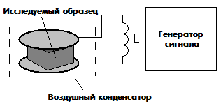
Capacitive hygrometers, in their simplest form, are capacitors with air as the dielectric in the gap. It is known that the dielectric constant of air is directly related to humidity, and changes in the humidity of the dielectric lead to changes in the capacitance of the air capacitor.
A more complex version of the capacitive air gap humidity sensor contains a dielectric, with a dielectric constant that can change greatly under the influence of humidity. This approach makes the quality of the sensor better than just with air between the capacitor plates.

The second option is well suited for making measurements regarding the water content of solids. The object under study is placed between the plates of such a capacitor, for example, the object can be a tablet, and the capacitor itself is connected to the oscillatory circuit and to the electronic generator, while the natural frequency of the resulting circuit is measured, and the capacitance obtained by introducing the sample under study is “calculated” from the measured frequency.
Of course, this method also has some disadvantages, for example, if the sample humidity is below 0.5%, it will be inaccurate, in addition, the measured sample must be cleaned of particles with a high dielectric change during the course of the study.

The third type of capacitive humidity sensor is the capacitive thin film hygrometer. It includes a substrate on which two comb electrodes are deposited. Comb electrodes play the role of plates in this case. For the purpose of thermal compensation, two additional temperature sensors are additionally introduced into the sensor.

Such a sensor includes two electrodes, which are deposited on a substrate, and on top of the electrodes themselves, a layer of material is applied, which is distinguished by a rather low resistance, however, which varies greatly depending on humidity.

A suitable material in the device may be alumina. This oxide absorbs water well from the external environment, while its resistivity changes markedly. As a result, the total resistance of the measurement circuit of such a sensor will significantly depend on humidity. So, the magnitude of the flowing current will indicate the level of humidity. The advantage of sensors of this type is their low price.
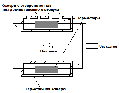
The thermistor hygrometer consists of a pair of identical thermistors. By the way, we recall that - this is a nonlinear electronic component, the resistance of which strongly depends on its temperature.
One of the thermistors included in the circuit is placed in a sealed chamber with dry air. And the other is in a chamber with holes through which air enters it with a characteristic humidity, the value of which needs to be measured. Thermistors are connected in a bridge circuit, voltage is applied to one of the diagonals of the bridge, and readings are taken from the other diagonal.
In the case when the voltage at the output terminals is zero, the temperatures of both components are equal, hence the humidity is the same. In the case when a non-zero voltage is obtained at the output, this indicates the presence of a difference in humidity in the chambers. So, according to the value of the voltage obtained during the measurements, the humidity is determined.
An inexperienced researcher may have fair question, why does the temperature of the thermistor change when it interacts with moist air? But the thing is that with an increase in humidity, water begins to evaporate from the thermistor case, while the temperature of the case decreases, and the higher the humidity, the more intense the evaporation occurs, and the faster the thermistor cools.
4) Optical (condensation) humidity sensor
This type of sensor is the most accurate. The operation of an optical humidity sensor is based on a phenomenon related to the concept of “dew point”. At the moment the temperature reaches the dew point, the gaseous and liquid phases are in thermodynamic equilibrium.
So, if you take glass and install it in a gaseous medium, where the temperature at the time of the study is above the dew point, and then start the process of cooling this glass, then at a specific temperature value, water condensate will begin to form on the surface of the glass, this water vapor will begin to pass into the liquid phase . This temperature will be just the dew point.
So, the dew point temperature is inextricably linked and depends on such parameters as humidity and pressure in the environment. As a result, having the ability to measure pressure and dew point temperature, it will be easy to determine humidity. This principle is the basis for the operation of optical humidity sensors.

The simplest circuit of such a sensor consists of an LED shining on a mirror surface. The mirror reflects the light, changing its direction, and directing it to the photodetector. In this case, the mirror can be heated or cooled by means of a special high precision temperature control device. Often such a device is a thermoelectric pump. Of course, a temperature sensor is installed on the mirror.
Before starting measurements, the mirror temperature is set to a value that is known to be higher than the dew point temperature. Next, the gradual cooling of the mirror is carried out. At the moment when the temperature starts to cross the dew point, water drops will immediately begin to condense on the surface of the mirror, and the light beam from the diode will break because of them, scatter, and this will lead to a decrease in the current in the photodetector circuit. Through feedback, the photodetector interacts with the mirror temperature controller.
So, based on the information received in the form of signals from the photodetector, the temperature controller will keep the temperature on the mirror surface exactly equal to the dew point, and the temperature sensor will accordingly show the temperature. So, with known pressure and temperature, you can accurately determine the main indicators of humidity.
The optical humidity sensor has the highest accuracy, unattainable by other types of sensors, plus the absence of hysteresis. The disadvantage is the highest price of all, plus high power consumption. In addition, it is necessary to ensure that the mirror is clean.
The principle of operation of an electronic air humidity sensor is based on a change in the concentration of electrolyte covering any electrical insulating material. There are such devices with automatic heating with reference to the dew point.
Often the dew point is measured over a concentrated solution of lithium chloride, which is very sensitive to minimal changes in humidity. For maximum convenience such a hygrometer is often additionally equipped with a thermometer. This device has high accuracy and low error. It is capable of measuring humidity regardless of the ambient temperature.

Simple electronic hygrometers are also popular in the form of two electrodes, which are simply stuck into the soil, controlling its moisture content according to the degree of conductivity, depending on this very moisture content. Such sensors are popular with fans, because you can easily set up automatic watering of a garden bed or flower in a pot, in case there is no time or is not convenient to water manually.
Before buying a sensor, consider what you will need to measure, relative or absolute humidity, air or soil, what the measurement range is expected to be, whether hysteresis is important, and what accuracy is needed. The most accurate sensor is optical. Pay attention to the IP protection class, the operating temperature range, depending on the specific conditions where the sensor will be used, whether the parameters are right for you.
This article arose in connection with the construction of an automatic watering machine for the care of indoor plants. I think that the watering machine itself may be of interest to a do-it-yourselfer, but now we will talk about a soil moisture sensor. https://website/
 |
 |
 |
 |
Of course, before reinventing the wheel, I went over the Internet.
Industrial-made humidity sensors turned out to be too expensive, and I never managed to find detailed description at least one such sensor. The fashion for trading "pig in bags", which came to us from the West, seems to have already become the norm.
Although there are descriptions of home-made amateur sensors on the network, they all work on the principle of measuring soil resistance to direct current. And the very first experiments showed the complete failure of such developments.
Actually, this did not really surprise me, since I still remember how, as a child, I tried to measure the resistance of the soil and discovered in it ... an electric current. That is, the arrow of the microammeter recorded the current flowing between two electrodes stuck into the ground.
The experiments, which took a whole week, showed that soil resistance can change quite quickly, and it can periodically increase and then decrease, and the period of these fluctuations can be from several hours to tens of seconds. In addition, in different flower pots, soil resistance varies in different ways. As it turned out later, the wife selects an individual composition of the soil for each plant.
At first, I completely abandoned the measurement of soil resistance and even began to build an induction sensor, as I found an industrial humidity sensor on the network, about which it was written that it was induction. I was going to compare the frequency of the reference oscillator with the frequency of another oscillator, the coil of which is dressed on a plant pot. But, when I started to prototype the device, I suddenly remembered how I once got under the “step voltage”. This prompted me to another experiment.

And indeed, in all found on the net makeshift designs, it was proposed to measure the resistance of the soil to direct current. But what if you try to measure the resistance to alternating current? Indeed, in theory, then the flowerpot should not turn into a "battery".
Collected the simplest circuit and immediately tested on different soils. The result was reassuring. No suspicious encroachments in the direction of increasing or decreasing resistance were found even for several days. Subsequently, this assumption was confirmed on an operating watering machine, the operation of which was based on a similar principle.
As a result of research, this circuit appeared on a single microcircuit. Any of the listed microcircuits will do: K176LE5, K561LE5 or CD4001A. We sell these microcircuits for only 6 cents.
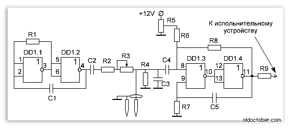
The soil moisture sensor is a threshold device that responds to changes in AC resistance (short pulses).
A master oscillator is assembled on the elements DD1.1 and DD1.2, which generates pulses with an interval of about 10 seconds. https://website/
Capacitors C2 and C4 are separating. They do not pass into the measuring circuit D.C. that the soil generates.
Resistor R3 sets the threshold, and resistor R8 provides the hysteresis of the amplifier. Trimmer resistor R5 sets the initial offset at the input DD1.3.
Capacitor C3 is anti-interference, and resistor R4 determines the maximum input resistance of the measuring circuit. Both of these elements reduce the sensitivity of the sensor, but their absence can lead to false positives.
You should also not choose the supply voltage of the microcircuit below 12 Volts, as this reduces the actual sensitivity of the device due to a decrease in the signal-to-noise ratio.
Attention!
I don't know if prolonged exposure to electrical pulses can have a detrimental effect on plants. This scheme was used only at the stage of development of the watering machine.
In order to water the plants, I used a different scheme, which generates only one short measuring pulse per day, timed to coincide with the time of watering the plants.
Connect the Arduino to the FC-28 Soil Moisture Sensor to determine when your soil under your plants needs water.
In this article, we are going to use the FC-28 Soil Moisture Sensor with Arduino. This sensor measures the volumetric water content of the soil and gives us the moisture level. The sensor gives us analog and digital data at the output. We are going to connect it in both modes.
The soil moisture sensor consists of two sensors that are used to measure the volumetric water content. Two probes allow the current to pass through the soil, which gives a resistance value, which ultimately allows the moisture value to be measured.
When there is water, the soil will conduct more electricity, which means there will be less resistance. Dry soil is a poor conductor of electricity, so when there is less water, the soil conducts less electricity, which means more resistance.
The FC-28 sensor can be connected in analog and digital modes. We will connect it first in analog mode and then in digital mode.
Specification
FC-28 Soil Moisture Sensor Specifications:
Pinout
Soil moisture sensor FC-28 has four pins:

The module also contains a potentiometer that will set the threshold value. This threshold value will be compared on the LM393 comparator. The LED will signal us the value above or below the threshold.
To connect the sensor in analog mode, we need to use the analog output of the sensor. Soil moisture sensor FC-28 accepts analog output values from 0 to 1023.
Humidity is measured as a percentage, so we will compare these values from 0 to 100 and then display them on the serial monitor. You can set different moisture values and turn the water pump on/off according to these values.

Connect the soil moisture sensor FC-28 to the Arduino as follows:
For the analog output, we write the following code:
int sensor_pin = A0; int output_value ; void setup() ( Serial.begin(9600); Serial.println("Reading From the Sensor ..."); delay(2000); ) void loop() ( output_value= analogRead(sensor_pin); output_value = map(output_value ,550,0,0,100); Serial.print("Mositure: "); Serial.print(output_value); Serial.println("%"); delay(1000); )
First of all, we defined two variables, one for the contact of the soil moisture sensor and the other for storing the output of the sensor.
int sensor_pin = A0; int output_value ;
In the setup function, the command Serial.begin(9600) will help in communication between Arduino and serial monitor. After that, we will print “Reading From the Sensor ...” on the normal display.
Void setup() ( Serial.begin(9600); Serial.println("Reading From the Sensor ..."); delay(2000); )
In the loop function, we will read the value from the analog output of the sensor and store the value in a variable output_value. Then we will compare the output values from 0-100 because humidity is measured in percentage. When we took readings from dry ground, the sensor value was 550, and during wet ground the sensor value was 10. We compared these values to get the moisture value. After that, we printed these values on the serial monitor.
void loop() ( output_value= analogRead(sensor_pin); output_value = map(output_value,550,10,0,100); Serial.print("Mositure: "); Serial.print(output_value); Serial.println("%") ;delay(1000); )To connect the FC-28 soil moisture sensor in digital mode, we will connect the sensor's digital output to an Arduino digital pin.
The sensor module contains a potentiometer which is used to set the threshold value. The threshold value is then compared with the sensor output value using the LM393 comparator, which is placed on the FC-28 sensor module. The LM393 comparator compares the output value of the sensor and the threshold value, and then gives us the output value through a digital output.
When the sensor value is greater than the threshold value, the digital output will give us 5V and the sensor LED will light up. Otherwise, when the sensor value is less than this threshold value, 0V will be transmitted to the digital output and the LED will not light up.
The connections for the soil moisture sensor FC-28 and Arduino in digital mode are as follows:

The code for digital mode is below:
intled_pin=13; int sensor_pin=8; void setup() ( pinMode(led_pin, OUTPUT); pinMode(sensor_pin, INPUT); ) void loop() ( if(digitalRead(sensor_pin) == HIGH)( digitalWrite(led_pin, HIGH); ) else ( digitalWrite(led_pin, LOW); delay(1000); ) )
First of all, we initialized 2 variables to connect the LED output and the digital output of the sensor.
int led_pin = 13; int sensor_pin = 8;
In the setup function, we declare the LED pin as an output pin, because we will turn on the LED through it. We declared the sensor pin as an input pin, because the Arduino will receive values from the sensor through this pin.
Void setup() ( pinMode(led_pin, OUTPUT); pinMode(sensor_pin, INPUT); )
In the loop function, we read from the output of the sensor. If the value is higher than the threshold value, then the LED will turn on. If the sensor value is below the threshold value, the indicator will turn off.
Void loop() ( if(digitalRead(sensor_pin) == HIGH)( digitalWrite(led_pin, HIGH); ) else ( digitalWrite(led_pin, LOW); delay(1000); ) )
This concludes the introductory lesson on working with the FC-28 sensor for Arduino. Good luck with your projects.


