Hi friends! Surely one of you have already read or personally faced the electromagnetic accelerator Gauss, which is more famous for the "Gauss gun".
The traditional Gaussian gun is based on the use of hard-to-reach or rather expensive capacitors of high capacity, also for the implementation of proper charging and a shot requires some blockage (diodes, thyristors and so on). It can be quite difficult for people who do not understand anything in electronics, but the desire to experiment does not allow to sit still. In this article, I will try in detail to tell about the principle of work of the gun and how you can collect a simplified to a minimum accelerator Gauss.
The main part of the cannon is the coil. As a rule, it is shaking independently on a dielectric non-magnetic rod, which in diameter slightly exceeds the diameter of the projectile. In the proposed design, the coil can be cold even "on the eyes", because the principle of operation simply does not allow any calculations. It is enough to produce a copper or aluminum wire with a diameter of 0.2-1 mm in a varnish or silicone insulation and to wind on the trunk of 150-250 turns so that the length of the winding of one row was about 2-3 cm. You can use the finished solenoid.

In classic cannons, this is achieved due to accurate calculations, the use of thyristors and other components that "will" impetum the right moment. We will simply break the chain "when it will happen." For emergency breaking of an electrical circuit in everyday life, fuses are used in everyday life, they can be used in our project, but it is more appropriate to replace them with light bulbs from the Christmas Garland. They are designed to be powered by a low voltage, so when nutrition from the network 220V instantly burn out and break the chain.


So, we will analyze everything in order. Charging guns running from 220 volts. Charging consists of a condenser 1.5 μF 400 V. Diodes 1N4006. Voltage at the output 350 V.

Next is the current-limiting load - H1, in my case the incandescent lamp, but you can use a powerful resistor of 500 - 1000 ohms. The S1 key limits the charging of the condests. S2 key gives a discharge powerful current to the solenoid, so S2 must withstand a high current, in its case I used the button from the electrical panel.

Capacitors C1 and C2, each 470 μF 400 V. in the amount is obtained by 940 μF 400 V. Constrators need to be observing polarity and voltage on them during charging. Control voltage on them can be voltmeter.

And now the most complex in our design Gauss cannon is a solenoid. It is wound on a dielectric rod. The inner diameter of the barrel is 5-6 mm. Wire used PAL 0.5. 1.5 cm coil thickness. Length 2 cm. Moting solenoid, you need to isolate with super glue.

To accelerate our electromagnetic Gauss gun, we will trim nails or homemade bullets with a thickness of 4-5 mm, long with the coil. Lighter bullets fly to a greater distance. Heavy fly less, but they have more energy. My Gauss Gane breaks beer banks and shoots 10-12 meters depending on the bullet.

And even, for the accelerator, it is better to pick up wires to the wires that there are less resistance in the chain. Be extremely careful! During the invention of the accelerator, I had a current several times, comply with the rules of electrical safety and pay attention to the reliability of isolation. Good luck in creativity.
Discuss the Gauss Article
.
In this article, Konstantin, the workshop of HOW-TODO, will show how to make a portable Gauss gun.
The project was made simply by Fan, so the goals to establish any records in the Gaussian building was not.


We charge the capacitor with high voltage and discharge it to the coil from copper wirelocated on the trunk.
When the current flows through it, a powerful electromagnetic field is created. The bullet from the ferromagnet is drawn into the trunk. The capacitor charge is spent very quickly and, ideally, the current over the coil ceases to flow at the moment when the bullet is in the middle.

Before moving to the assembly, you should warn you that you need to work with high voltage very carefully.
Especially when using such large capacitors, it can be quite dangerous.

First, due to simplicity. Electronics in it is practically elementary.
When making a multistage system, you need to somehow switch coils, counting them, set sensors.


It was necessary to paint in half to leaning out the window.


Therefore, we take a finger battery.


This could be avoided, whether a converter with one-semi-period rectifier.
Attempts to remake the existing success did not bring.
You can proceed to the manufacture of bullets. They must be magnetic.


We finish assembling the sizing case and coils.


The homemade presented for you Konstantin, HOW-TODO workshop.
Hello everyone. In this article, we consider how to make a portable electromagnetic gun Gauss, assembled using a microcontroller. Well, about Gauss's guns, I, of course, got excited, but the fact that it is an electromagnetic cannon, there is no doubt. This device on the microcontroller was designed to train novice programming microcontrollers on the descriptive example electromagnetic gun Do it yourself. Some constructive moments as in the electromagnetic gun Gauss and the microcontroller program.
From the very beginning it is necessary to determine the diameter and length of the trunk of the gun itself and the material from which it will be made. I applied a plastic case with a diameter of 10 mm from under a mercury thermometer, since he was lying around without a case. You can use any available material with non-ferromagnetic properties. This is glass, plastic, copper tube etc. The length of the trunk may depend on the amount of electromagnetic coils used. In my case, four electromagnetic coils are used, the length of the barrel was twenty centimeters.

As for the diameter of the applied tube, then during operation, the electromagnetic gun showed that the diameter of the barrel relative to the projectile applied is to be taken into account. Simply put, the diameter of the barrel should not be much higher than the diameter of the projectile applied. Ideally, the stem of the electromagnetic cannon must approach the shell itself.
The material for the creation of shells served as an axis from the printer with a diameter of five millimeters. Of this material And five 2,5 centimeters long blanks were made. Although steel blanks can also be applied, say, from wire or electrode - which is found.
You need to pay attention and weight of the projectile itself. Weight if possible should be small. My shells are slightly heavy.

Before creating this gun, experiments were carried out. An empty paste from the handle was used as a trunk, as a shell - a needle. The needle easily punched the cover of the magazine installed near the electromagnetic gun.
Since Gauss's original electromagnetic gun is built according to the principle of the charge of a capacitor with a large voltage, the order of three hundred volts, then in order to security, beginner radio amateurs should be powered by its low voltage, about twenty volts. Low voltage leads to the fact that the range of the projectile is not very large. But again, it all depends on the number of electromagnetic coils used. The more electromagnetic coils apply, the more it turns out the acceleration of the projectile in the electromagnetic cannon. The diameter of the barrel is also important (the smaller the diameter of the trunk, the one is flying next) and the quality of winding directly by the electromagnetic coils themselves. Perhaps the electromagnetic coils are the most basic in the device of an electromagnetic gun, you need to pay serious attention to achieving the maximum shell flight.
I will give the parameters of your electromagnetic coils, you can have others. The coil is wound with a wire with a diameter of 0.2 mm. The winding length of the electromagnetic coil layer is two centimeters and contains six such rows. I did not insulate every new layer, but I started winding a new layer to the previous one. Due to the fact that electromagnetic coils are powered by low voltage, you need to get the maximum quality of the coil. Therefore, all the turns are wound tightly to each other, the turn to the twist.

As for the feeding device, then special explanations Not needed. Everything sold out of the waste of foil textolite remaining from production printed circuit board. In the figures, everything is displayed in detail. The heart of the feeder is the SG90 servo driven by a microcontroller.

The feed rod is made of a steel bar with a diameter of 1.5 mm, at the end of the rod, a nut M3 nut for clutch with a servo. On the rocker of the servo to increase the shoulder, a copper wire with a diameter of 1.5 mm was installed on the first ends.
This simple device assembled from the primary materials is quite enough to submit a projectile to the stem of the electromagnetic gun. The feeding rod must completely exit the boot store. A closed brass rack with an inner diameter of 3 mm and a length of 7 mm served as a guide for the feed rod. It was a pity to throw away, so it was useful, actually, like pieces of foil textolite.
The ATMEGA16 microcontroller program was created in Atmelstudio, and is completely open project For you. Consider some settings in the microcontroller program that will have to produce. For maximum efficient work The electromagnetic cannon will need to configure the time of operation of each electromagnetic coil in the program. The setting is made in order. First, the first coil is in the diagram, do not connect all the others. Specify the time of work in the program (in milliseconds).
We flash the microcontroller, and run the program on the microcontroller. The coil's efforts should be enough to draw the shell and give the initial acceleration. Having achieved the maximum departure of the projectile, adjusting the time of the coil in the microcontroller program, connect the second coil and also customize the time, achieving an even greater range of projectile flight. Accordingly, the first coil remains enabled.
Porta | \u003d (1 porta & \u003d ~ (1
In this way, you set up the work of each electromagnetic coil, connecting them in order. As the number of electromagnetic coils in the device of the Gauss electromagnetic can be increased and, accordingly, the projectile range should also increase.
This painstaking procedure for setting up each coil can be avoided. But for this you will have to upgrade the device of the electromagnetic gun itself, setting the sensors between the electromagnetic coils to track the movement of the projectile from one coil to the other. Sensors in combination with the microcontroller will allow not only to simplify the process of setting, but also increase the range of the projectile. I did not make data and complicate the microcontroller program. The goal was to implement an interesting and simple project using a microcontroller. As far as it is interesting, to judge, of course, you. I will say honestly, I was happy as a child, "ground" from this device, and I have ripened the idea of \u200b\u200ba more serious device on the microcontroller. But this is the topic for another article.
Program and scheme -
9,830 ViewsSatisfied with the powerful model of the famous Gauss cannon, which can be made with their own hands from the girlfriend. This homemade Gauss cannon is made very simply, has a light design, all the parts used will have every amateur of the homemade and the radio amateur. Using the coil calculation program, you can get the maximum power.
The shape of the body may be any, not necessarily adhere to the presented scheme. What would give the body aesthetic species, you can paint it with paint from the canister.


To begin with, condensers, in this case, they were fixed on plastic ties, but you can come up with another mount.

Then set the cartridge for the heat lamp on the outside of the case. Do not forget to connect two wires to it for power.


Then inside the housing battery compartment And fix it, for example, tree self-assembly or in another way.

To calculate the Gauss coil, you can use the FEMM program, you can download the FEMM program at this link https://code.google.com/archive/p/femm-coilgun
The program is very easy to use, in the template you need to enter the necessary parameters, load them into the program and at the output we obtain all the characteristics of the coil and the future cannon as a whole, up to the projectile speed.
So let's start winding! First you need to take the cooked tube and wind on it using PVA glue so that the outer diameter of the tube was 6 mm.


Then we drill holes in the center of the segments and planted from the tube. With the help of hot glue fix them. The distance between the walls should be 25 mm.


Place the coil on the trunk and proceed to the next stage ...


We collect the circuit inside the housing by mounted installation.

Then we set the button to the housing, drill two holes and do the wires to the coil there.

To simplify use, you can make a stand for a gun. In this case, it was made of wooden bar. IN this variant The boots were left to the edges of the trunk, it is necessary in order to adjust the coil, moving the coil, you can achieve the highest power.

Shells for guns are made of metal nail. Segments are made with a length of 24 mm and a diameter of 4 mm. Projectile billets need to be sharpened.


Subscribe to news
The scope of the use of thermal electrops is quite wide. Industrial units are used to warm production, warehouse and even residential premises. And on small squares you can do and homemade design The heat generator, which is performed by the power to protrud a garage or country house.
If electrical is made heat gun With your own hands, it will cost it literally a penny. However, in the manufacture useful homemade It is required to follow the rules. Only in this case, the device will not be worse than the factory product.
We will tell you how to competently make the electric tub. From the article we suggested, you will learn what materials and components will be required to build an aggregate. Our tips will help in the manufacture of efficient and economical equipment.
Unlike other varieties of heat pipes, electrical appliance You can make almost any homemade master, familiar with the Aza electronics.
Although the electric power efficiency is much lower than diesel or, it does not highlight the burning products harmful to health and can be installed in any room - a residential building, greenhouse, utility extensions.
The power of industrial cannons varies from 2 to 45 kW, with the number of heating elements in them can reach up to 15 pcs
Consider how the electric unit works.
Any electric tube consists of three main components: housings, electric motor with a fan and heating element. The varieties of this type of instruments are described in detail on the classification and principles of the heat guns.
Additionally, the device can be equipped with any "bonuses" from factory units - speed switch, heat-regulator, room thermostat, body heating sensor, engine protection and other elements, but they increase not only comfort and safety during operation, and the cost of homemade.

Air heating rate throughout the size of the room depends on the number and power of the heating elements - the more their area, the more active the heat transfer will occur
The electric cannon works like this:
If the device is equipped with a thermostatic element, it will stop the operation of the heater when the programmed temperature is reached. In primitive devices, control the heating will have to be independently.
The main plus of the heat generator is the possibility of its use in any room where there is a network of at least 220 W.
Such devices even in homemade versions are mobile, weigh a little and completely able to heat the area up to 50 m 2 (theoretically, it is possible and more, but with high-power devices, it is better not to experiment and buy a finished unit, and the gun from 5 kW will already be requested to connect to a three-phase network ).

The operating characteristics of the device must correspond to the heated area. The average for every 10 m2 will require 1 kW, but much depends on the room itself - building materials, glazing quality and insulation
Pluses of a homemade electric gun:
Of the minuses, it is possible to note the high consumption of electricity (the amount depends on the power of the engine and the Tan). In addition, the operation of the fan is rather sonorous, and the more the scope of "wings" and the speed of rotation, the stronger the noise will be.
Well, any lack of homemade electrical device - The probability of error when assembling or connecting, which can cause closure on the network, shock and self-burning the instrument.
The most difficult stage when assembling the instrument is to make the correct electrical installation scheme to connect the device to the network. Therefore, we propose to take advantage of the ready-made example by taking it as the basis of the future heat pipe. As can be seen in the diagram, the toggle switch and thermostats must be connected in series, and the chain is closed on a tane and an electric motor with a fan.

The thermostat is responsible for the level of heat heating and the automatic disconnection of the chain when the desired temperature is reached in the room, and if you exclude it from the schema, you will have to follow the equipment yourself to avoid overheating.
Consider the features of the manufacture of two simple options.
For the body of the future cannon, you can pick up a segment of a metal or asbestos-cement pipe of a suitable diameter. Customized the size best on the spoke of "wings" of the fan, because it should block one of the ends of the device.
If desired, the heat generator can be made of a small metal tank, a galvanized bucket, an old pan or a spent gas cylinder, the main thing is that the walls of the "casing" are not thin.

The power of the fan for the thermal gun does not have a decisive value, because the heating rate of air depends solely on the agent, and the impeller only dispels the warm stream by the room, so you can safely take a fragment from household exhaust or vacuum cleaner
As for the Tan, you can remove this element with the tile or boiler, or purchase in the store - now it is not a problem to find a heater of any form. If you buy ready, the best option It will become an ordinary part specifically designed to quickly warm the moving air flow.

The power of the TEN should be knocked out on its case or registered in the accompanying documentation, but if it is an old device, you can measure its resistance to the multimeter and determine the power by the above formula.
In addition to the three main elements (enclosures, engine and a tan), it will take a three-in-room cable, bolts, and (UZO), disconnecting the network in a dangerous situation.
Phased work plan:
After checking the isolation of all connections, you can make a trial launch of the device. If everything is assembled correctly, when the plug is turned on into the socket at one end of the gun, the fan will start rotating, and the warm air will go from the other, gradually gaining the temperature.
If you are in your arsenal homemade Masters There was no old one household applianceFrom where you can remove the TEN, and you do not want to buy a ready-made heater for any reason, you can make it yourself from the nichrome spiral.
In addition to low cost, such an element has an important advantage over factory copies - the ability to independently adjust right size According to the body format and increase the heating rate to a safe maximum.

The devices with an open spiral by default are shamelessly, so independent manufacture Tan requires good work skills with electrician
It will take a nichrome wire with a suitable diameter of the resistance to the homemade. And it depends on the planned power of your device (for household devices and the network 220 is preferably not exceeding 5 kW).
For example, for a gun up to 2 kW, it will take a wire with a resistance by 27-30 ohms, which you need to climb on a ceramic rod or another heat-resistant material (as a last resort, you can split the refractory brick plate).

The size of the spiral can be determined by an experimental way, selecting the number of turns according to the degree of heating the wire, but it is much easier to use the table, where D is the diameter of the rod to which the wire with length L will be wound
Another option is to make it easy to make a homemade Ten from a small segment of asbestos-cement pipe, placing an inward coil spiral from the same nichrome wire. You can arrange the turns horizontally and vertically to cover the large area.

Homemade TEN by 1.6 kW of six spiral fragments, which almost completely overlap the lumen of the pipe, which ensures fast heating of the air flow
The design assembly is performed by analogy with the instructions described above, so we will not be repeated at the same moments, but we will consider the nuances of the joining of the homemade Tan:
A significant drawback of such a self-made, in addition to the energy consumption and other minuses of electricians, is an unpleasant lifting smell, which arises from the combustion of dust on an open spiral.
Rules for safe work The homemade cannon is practically no different from the operation of other electrical appliances: it is necessary to avoid tipping the device and penetrate moisture inside, do not touch the heated body and not leave the unit to work unattended.
Of important features - Before shutdown, you must first stop the work of Tan, give a fan for a few minutes to work the fan and only then pull the plug from the power grid.

Homemade heat pipes without thermostators are not intended for long-term work - they can cause a closure on the network or ignite from the hot spirals, in addition, the electrical appliances are strongly overpowered by air, so the room is recommended to ventilate more
Self-timers assembly tips:
Grounding the metal body of the instrument will help to avoid accidental lesion.
And the last advice - if your knowledge is in an electrician at the level of the amateur, then before connecting the homemade apparatus to the network, consult with the master that the professional look will appreciate the performance and safety of your creation.
With the criteria for choosing an electric fan heater plant, I will familiarize yourself. If you doubt your own abilities or you do not have time to build homemakes, read the material recommended by us.
Video # 3. Heat pipe for 2 kW from the old fire extinguisher:
As you can see, make it with your own hands the electric cannon is really easy. But if you are not sure about your skills to work with the electrical part, it is better to consult with an experienced electrician or buy a finished device.
If you have recommendations or arose questions during the familiarization with the material, leave posts in the block below. Comment, please see the material, place the photo on the topic. Perhaps your tips will be useful to site visitors.
The project was started in 2011. It was a project that implies a fully autonomous automatic system for entertainment purposes, with a projectile energy of about 6-75, which is comparable to pneumatics. It was planned 3 automatic steps with starting from optical sensors, plus a powerful drum injector sent to the store in the barrel.
The layout was planned such:
Ie Classic Bull-Dad, which made it possible to make heavy batteries in the butt and thereby shift the center of gravity closer to the handle.
The scheme looks like this:
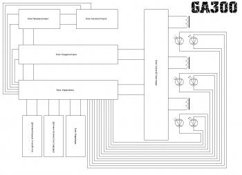
The control unit later was divided into the power block control unit and the general control unit. The condenser block and the switching unit were found in one. Also, backup systems were developed. Of these, a power block control unit, a power unit, a converter, a voltage distributor, a part of the indication block were collected.
It is a 3 comparator with optical sensors.

Each sensor has its own comparator. This is done to increase reliability, so when you fail the single chip, only one step will refuse, and not 2. When overlapping the mechanical beam, the phototransistor resistance changes and the comparator is triggered. In classical thyristor switching, the control conclusions of thyristors can be connected directly to the outputs of comparators.
Sensors must be installed as follows:
And the device looks like this:

The power unit has the following simple scheme:

C1-C4 capacitors have 450V voltage and 560MKF capacity. VD1-VD5 diodes are applied by HER307 / As switching, the VT1-VT4 type 70TPS12 power thyristors are applied.

The collected block connected to the control unit in the photo below:

The converter was applied low-voltage, more about it can be found

The voltage distribution unit is implemented by a banal capacitor filter with a power switch and an indicator that is notified by the battery charge process. The unit has 2 outputs, the first power, the second to everything else. So it has conclusions for connecting a charger.

On the photo, the distribution unit is extreme right from above:

In the lower left corner, the backup converter, it was assembled by the simplest scheme on the NE555 and IRL3705 and has a power of about 40W. It was assumed to use it with a separate small battery, including the backup system if the main or discharge of the main battery is refused.
Using the backup converter, pre-checking coils were performed and the possibility of using lead batteries was checked. On the video one-stage model shoots into a pine board. A bullet with a special tip of an increased penetrative ability enters the tree by 5mm.
Within the project, a universal stage was developed as the main unit for the following projects.
This scheme is a block for an electromagnetic accelerator, on the basis of which you can collect a multistage accelerator with a number of steps to 20. The stage has classical thyristor switching and an optical sensor. Energy inflated into condensers - 100J. Efficiency about 2x percent.

70W converter with a specifying generator on the NE555 chip and the IRL3705 power transistor is used. A repeater is provided between the transistor and the output of the microcircuit on the complementary pair of the transistors required to reduce the load on the microcircuit. The comparator of the optical sensor is assembled on the LM358 chip, it controls a thyristor, connecting condensers to the winding when the sensor is passing. Parallel to the transformer and accelerating coil applied good tube chains.
Methods of increasing efficiency
The methods of increasing efficiency, such as magnetic core, coil cooling and energy recovery were considered. About the latter will tell more.
Gaussan has a very small efficiency, people working in this area have long been looking for ways to increase efficiency. One of these methods is recovery. Its essence is to return the non-used energy in the coil back into the capacitors. Thus, the energy of the induced reverse impulse does not go anywhere and does not cling the shell with a residual magnetic field, and pumps back to the capacitors. In this way, you can return to 30 percent of the energy, which in turn will increase the efficiency of 3-4 percent and reduce recharging time, increasing the rate of fire in automatic systems. And a scheme on the example of a three-step accelerator.

T1-T3 transformers are used for galvanic junction in the thyristor control circuit. Consider the work of one step. We supply the charge voltage of capacitors, through the VD1 capacitor C1 charging up to the rated voltage, the gun is ready for the shot. When the pulse is applied to the input input, it is transformed with the T1 transformer, and enters the control outputs VT1 and VT2. VT1 and VT2 open and connect the coil L1 with the C1 condenser. The graph below shows the processes during a shot.

Most of all, we are interested in the part starting from 0.40 ms, when the voltage becomes negative. It is this tension with the help of recovery that can be caught and returned to condensers. When the voltage becomes negative, it passing through the VD4 and VD7 is pumped into the accumulator of the next stage. This process also cuts off part of the magnetic pulse, which allows you to get rid of the braking residual effect. The remaining steps work like the first.
Project status
The project and my developments in this direction were generally suspended. Probably in the near future I will continue my work in this area, but I do not promise anything.
| Designation | A type | Nominal | number | Note | Score | My notebook | |
|---|---|---|---|---|---|---|---|
| Power control unit | |||||||
| Operational amplifier | LM358. | 3 | In notebook | ||||
| Linear regulator | 1 | In notebook | |||||
| Phototransistor | SFH309. | 3 | In notebook | ||||
| Light-emitting diode | SFH409. | 3 | In notebook | ||||
| Capacitor | 100 μF | 2 | In notebook | ||||
| Resistor | 470 Oh. | 3 | In notebook | ||||
| Resistor | 2.2 com | 3 | In notebook | ||||
| Resistor | 3.5 com | 3 | In notebook | ||||
| Resistor | 10 com | 3 | In notebook | ||||
| Silence block | |||||||
| VT1-VT4. | Thyristor | 70tps12 | 4 | In notebook | |||
| VD1-VD5 | Rectifying diode | HER307. | 5 | In notebook | |||
| C1-C4. | Capacitor | 560 ICF 450 V | 4 | In notebook | |||
| L1-L4. | Inductor | 4 | In notebook | ||||
LM555. | 1 | In notebook | |||||
| Linear regulator | L78S15CV | 1 | In notebook | ||||
| Comparator | LM393. | 2 | In notebook | ||||
| Bipolar transistor | MPSA42. | 1 | In notebook | ||||
| Bipolar transistor | MPSA92. | 1 | In notebook | ||||
| Mosfet transistor | IRL2505 | 1 | In notebook | ||||
| Stabilirton | BZX55C5V1. | 1 | In notebook | ||||
| Rectifying diode | HER207. | 2 | In notebook | ||||
| Rectifying diode | HER307. | 3 | In notebook | ||||
| Diode Schottki | 1N5817. | 1 | In notebook | ||||
| Light-emitting diode | 2 | In notebook | |||||
| 470 μF. | 2 | In notebook | |||||
| Electrolytic condenser | 2200 μF. | 1 | In notebook | ||||
| Electrolytic condenser | 220 μF. | 2 | In notebook | ||||
| Capacitor | 10 μF 450 V | 2 | In notebook | ||||
| Capacitor | 1 μF 630 V | 1 | In notebook | ||||
| Capacitor | 10 NF | 2 | In notebook | ||||
| Capacitor | 100 NF. | 1 | In notebook | ||||
| Resistor | 10m | 1 | In notebook | ||||
| Resistor | 300 com | 1 | In notebook | ||||
| Resistor | 15 com | 1 | In notebook | ||||
| Resistor | 6.8 com | 1 | In notebook | ||||
| Resistor | 2.4 com | 1 | In notebook | ||||
| Resistor | 1 com | 3 | In notebook | ||||
| Resistor | 100 Oh. | 1 | In notebook | ||||
| Resistor | 30 Oh. | 2 | In notebook | ||||
| Resistor | 20 Oh. | 1 | In notebook | ||||
| Resistor | 5 Ohm. | 2 | In notebook | ||||
| T1. | Transformer | 1 | In notebook | ||||
| Voltage distribution unit | |||||||
| VD1, VD2. | Diode | 2 | In notebook | ||||
| Light-emitting diode | 1 | In notebook | |||||
| C1-C4. | Capacitor | 4 | In notebook | ||||
| R1 | Resistor | 10 Oh. | 1 | In notebook | |||
| R2 | Resistor | 1 com | 1 | In notebook | |||
| Switch | 1 | In notebook | |||||
| Battery | 1 | In notebook | |||||
| Programmable timer and oscillator | LM555. | 1 | In notebook | ||||
| Operational amplifier | LM358. | 1 | In notebook | ||||
| Linear regulator | LM7812. | 1 | In notebook | ||||
| Bipolar transistor | BC547. | 1 | In notebook | ||||
| Bipolar transistor | BC307. | 1 | In notebook | ||||
| Mosfet transistor | AUIRL3705N. | 1 | In notebook | ||||
| Phototransistor | SFH309. | 1 | In notebook | ||||
| Thyristor | 25 A. | 1 | In notebook | ||||
| Rectifying diode | HER207. | 3 | In notebook | ||||
| Diode | 20 A. | 1 | In notebook | ||||
| Diode | 50 A. | 1 | In notebook | ||||
| Light-emitting diode | SFH409. | 1 | |||||
Hello everyone. In this article, we consider how to make a portable electromagnetic gun Gauss, assembled using a microcontroller. Well, about Gauss's guns, I, of course, got excited, but the fact that it is an electromagnetic cannon, there is no doubt. This device on the microcontroller was designed to train novice programming microcontrollers on the example of designing an electromagnetic gun with their own hands. Some constructive moments both in the electromagnetic gun of Gauss and in a microcontroller program.
From the very beginning it is necessary to determine the diameter and length of the trunk of the gun itself and the material from which it will be made. I applied a plastic case with a diameter of 10 mm from under a mercury thermometer, since he was lying around without a case. You can use any available material with non-ferromagnetic properties. This is glass, plastic, copper tube, etc. The length of the trunk may depend on the amount of electromagnetic coils used. In my case, four electromagnetic coils are used, the length of the barrel was twenty centimeters.

As for the diameter of the applied tube, then during operation, the electromagnetic gun showed that the diameter of the barrel relative to the projectile applied is to be taken into account. Simply put, the diameter of the barrel should not be much higher than the diameter of the projectile applied. Ideally, the stem of the electromagnetic cannon must approach the shell itself.
The material for the creation of shells served as an axis from the printer with a diameter of five millimeters. From this material and five 2,5 centimeters long duster were made. Although steel blanks can also be applied, say, from wire or electrode - which is found.
You need to pay attention and weight of the projectile itself. Weight if possible should be small. My shells are slightly heavy.

Before creating this gun, experiments were carried out. An empty paste from the handle was used as a trunk, as a shell - a needle. The needle easily punched the cover of the magazine installed near the electromagnetic gun.
Since Gauss's original electromagnetic gun is built according to the principle of the charge of a capacitor with a large voltage, the order of three hundred volts, then in order to security, beginner radio amateurs should be powered by its low voltage, about twenty volts. Low voltage leads to the fact that the range of the projectile is not very large. But again, it all depends on the number of electromagnetic coils used. The more electromagnetic coils apply, the more it turns out the acceleration of the projectile in the electromagnetic cannon. The diameter of the barrel is also important (the smaller the diameter of the trunk, the one is flying next) and the quality of winding directly by the electromagnetic coils themselves. Perhaps the electromagnetic coils are the most basic in the device of an electromagnetic gun, you need to pay serious attention to achieving the maximum shell flight.
I will give the parameters of your electromagnetic coils, you can have others. The coil is wound with a wire with a diameter of 0.2 mm. The winding length of the electromagnetic coil layer is two centimeters and contains six such rows. I did not insulate every new layer, but I started winding a new layer to the previous one. Due to the fact that electromagnetic coils are powered by low voltage, you need to get the maximum quality of the coil. Therefore, all the turns are wound tightly to each other, the turn to the twist.

As for the feeding device, there are no special explanations here. All sold out of the waste of foil textolite remaining from the production of printed circuit boards. In the figures, everything is displayed in detail. The heart of the feeder is the SG90 servo driven by a microcontroller.

The feed rod is made of a steel bar with a diameter of 1.5 mm, at the end of the rod, a nut M3 nut for clutch with a servo. On the rocker of the servo to increase the shoulder, a copper wire with a diameter of 1.5 mm was installed on the first ends.
This simple device assembled from the primary materials is quite enough to submit a projectile to the stem of the electromagnetic gun. The feeding rod must completely exit the boot store. A closed brass rack with an inner diameter of 3 mm and a length of 7 mm served as a guide for the feed rod. It was a pity to throw away, so it was useful, actually, like pieces of foil textolite.
The ATMEGA16 microcontroller program was created in Atmelstudio, and is a fully open project for you. Consider some settings in the microcontroller program that will have to produce. For the most efficient operation of the electromagnetic cannon, you will need to configure the operation of each electromagnetic coil in the program. The setting is made in order. First, the first coil is in the diagram, do not connect all the others. Specify the time of work in the program (in milliseconds).
Porta | \u003d (1<<1); // катушка 1
_delay_ms (350); / / working hours
We flash the microcontroller, and run the program on the microcontroller. The coil's efforts should be enough to draw the shell and give the initial acceleration. Having achieved the maximum departure of the projectile, adjusting the time of the coil in the microcontroller program, connect the second coil and also customize the time, achieving an even greater range of projectile flight. Accordingly, the first coil remains enabled.
Porta | \u003d (1<<1); // катушка 1
_delay_ms (350);
Porta & \u003d ~ (1<<1);
Porta | \u003d (1<<2); // катушка 2
_delay_ms (150);
In this way, you set up the work of each electromagnetic coil, connecting them in order. As the number of electromagnetic coils in the device of the Gauss electromagnetic can be increased and, accordingly, the projectile range should also increase.
This painstaking procedure for setting up each coil can be avoided. But for this you will have to upgrade the device of the electromagnetic gun itself, setting the sensors between the electromagnetic coils to track the movement of the projectile from one coil to the other. Sensors in combination with the microcontroller will allow not only to simplify the process of setting, but also increase the range of the projectile. I did not make data and complicate the microcontroller program. The goal was to implement an interesting and simple project using a microcontroller. As far as it is interesting, to judge, of course, you. I will say honestly, I was happy as a child, "ground" from this device, and I have ripened the idea of \u200b\u200ba more serious device on the microcontroller. But this is the topic for another article.
Program and scheme -
Gauss Gan do it yourself
Once it was already started to meet in one of the articles with Gauss cannons, or otherwise Gauss Gan. which are made do it yourself, In this article, I have another design and visitos of Gauss gun.
This gauss gun powered by battery in 12 volts. It can be seen in the picture.
This article can also be used as an instruction, as it describes the assembly of guns in detail.
Gun characteristics:
Mass: 2.5 kg
Starter speed: Approximately 9 m / s
Extra weight: 29 g
The kinetic energy of the projectile: approximately 1.17 J.
Charging time of the capacitors from the battery through the converter: 2 sec
Time charging capacitors from the network through the converter: about 30 seconds
Dimensions: 200x70x170 mm
This electromagnetic accelerator is able to shoot any metal shells that magnetic. Gauss cannon consists of coil and capacitors. When electric current flow through the coil, an electromagnetic field is formed, which in turn accelerates the metal shell. The destination is most different - mainly to scare your classmates. In this article, I will tell you how to make myself such a Gauss gun.
Structural scheme Gauss cannon

I would like to clarify the moment. On the structural scheme, the condenser is 450 volts. And from the multiplier, 500 volts are coming out. And the author is true? Well, the author did not take into account this. Let the condenser at least 500 volts.
And now the scheme itself is a multiplier:

In the scheme used field iRF transistor 3205. With this transistor charge rate 1000 μF capacitor for voltage 500 volts will be approximately equal to 2nd seconds (with battery 4 amps / hours). You can use the IRL3705 transistor, but the charging speed will be approximately 10 seconds. Here is the video operation of the converter:
In the multiplier, the video is the IRL3705 transistor, so the capacitors are charged for a long time. Later, I replaced IRL3705 on IRF 3205 Charging speed began to be equal to 2nd seconds.
Resistor R7. regulated output voltage from 50 to 900 volts; LED 1 shows when the capacitors charged to the desired voltage. If a multiplier transformer is noise, try to reduce the capacitor C1 capacitor, choke L1 is not required, C2 capacitor capacity can be reduced to 1000 μF, diodes D1 and D2 can be replaced with other diodes with similar characteristics. IMPORTANT! The S1 switch is clogged only after the power output voltage is applied. Otherwise, if you submit a voltage to the conclusions and the S1 switch will be closed, can fail the transistor due to a sharp voltage jump!
The scheme itself works simply: the UC3845 microcircuit produces rectangular pulses, which are fed to the valve of a powerful field transistor, which are amplified by amplitude and fed to the primary winding of the pulse transformer. Next, the impulsesaced by a pulsed transformer to amplitude 500-600 volts are straightened by a diode d2 and the capacitors are charged with a straightened voltage. The transformer is taken from a computer power supply unit. The diagram near the transformer shows a point. These points indicate the beginning of the winding. The method of winding the transformer is:
1 . Creames a transformer taken from an unnecessary computer BP (the largest transformer) in boiling water for 5-10 minutes, then carefully disassemble the W-shaped ferrite core and unwind completely transformer.
2
. First we wake half the secondary winding with a wire of a diameter of 0.5-0.7 mm. You need to wear out from the leg indicated on the point scheme.
Mottling 27 turns we take the wire without biting it, isolate 27 turns with paper or cardboard and remember which direction the wire was screwed. This is important !!! If the primary winding is wound in the other direction, then nothing will work, as currents will deduct !!!

3 . Next we wind the primary winding. It is winding up too from the start specified on the scheme. We wake it up in the same direction, in which the first part of the primary winding was wound. The primary winding consists of 6 wires soldy together and wound up with the 4th turns. We wash all 6 wires parallel to each other, smoothly laying out them with the 4th coils in two layers. Between the layers we lay the layer of insulating paper.
4 . Next, they have a secondary winding (27 more turns). We wind up the same way as before. And here is the transformer! It remains to collect the scheme itself. If the scheme is done correctly, the diagram works immediately without any settings.
Details for the converter:

For the converter, a powerful energy source is required as a battery for 4 amps / hour. The more powerful the battery, the faster the charging of the capacitors.
Here is the converter itself:

Printing fee Converter-bottom view:

This fee is quite big and leaning a little, I painted smaller card in Sprint-Layout:

For those who are not able to make a converter, there is a Gauss version of the gun from a network of ~ 220 volts. Here is a multiplier scheme from the network:

Diodes can be taken any, which keep the voltage above 600 volts, the capacitance of the capacitor is selected by experimentally from 0.5 to 3.3 μF.
If the scheme is created correctly, it will work immediately without any settings.
I have an 8th coil. It is wound with a copper lacquered wire with a diameter of 0.7 mm. The total length of the wire is about 90 meters.

Now when everything has been done left to assemble the gun itself. The total cost of the gun is about 1000 rubles. The cost was calculated like this:
For those who want to make the same cannon as I have a step-by-step instruction:
1) Drink a piece of plywood in size of 200x70x5 mm.
2) We make a special mount for the handle. You can make a handle from toy pistol, but I have a handle from the gun for insulin injection. Inside the handle set the button with two positions (three outputs).
3) Install the handle.
4) Making fastenings on the plywood for the converter.

5) Install the converter on the Phaneur.
6) We make a protective flap on the converter so that the projectile does not damage the converter.

7) Install the coil and all solder all the wires as on the structural scheme.

8) Make the hull from the Fiberboard

9) Install all switches in place, the battery is fixed by large screeds. That's all! The gun is ready! Shoots this gun here are such shells:

The diameter of the projectile is 10 mm, and the length is 50 mm. Weight 29 grams.
Gun with a raised body:

And at the end of a few video recordings
Here are the video of the Gauss Gauss Pushki.Dell in a box of corrugated cardboard
Shot to a tile with a thickness of 0.8 mm:


