Italian company BAXI S.p.A. has been manufacturing equipment for heating and hot water supply for over 50 years. The product range includes wall-mounted standard and condensing gas heating boilers, floor gas boilers with cast iron heat exchanger and electric storage water heaters.
The total annual turnover of the company is approximately 270 million euros. The company employs 800 people. More than 75% of our products are exported to 70 countries around the world.
BAXI company S.p.A. was founded in 1924 by the Austrian Westen family, which opened a factory for the production of enamelware in the city of Bassano Del Grappa.
In the period from 1978 to 1984, the company was part of the Zanussi group and was engaged in the production of gas boilers, electric water heaters, steel radiators and steel baths.
From 1984 to 1998, the company was called Ocean Idroclima and was part of the El.Fi group of companies. Since the mid-1980s, the active development of the export of manufactured products begins on a global scale.
A home heating system that works on the principle of floor heating is nowadays difficult to surprise anyone. More and more owners of suburban housing, if they have not yet switched, are seriously considering the prospects of switching to this efficient and comfortable scheme for transferring heat from boiler equipment to premises. One of the options is the organization of water "warm floors". Despite the considerable complexity of their installation, they are very popular due to their economical operation, and because of their compatibility with an existing hot water heating system, of course, after certain modifications of the latter.
In general, it is hardly worth starting an independent creation of water "warm floors" without having any experience in plumbing and general construction work. Every nuance is important here - from the choice of pipes and their layout, from the correct thermal insulation of the floor surface and pouring the screed - to the installation of the hydraulic part, followed by accurate debugging of the system. But this is how a typical Russian owner of a house works: he wants to try everything himself. And if the "hand is full", then many try to carry out such work on their own. To help them - this publication, which will consider one of the most important nodes of such a system. So, what is it for, how is it arranged and is it possible to make a mixing unit for a warm floor with your own hands at home.
The traditional heating system, which implies the installation of heat exchange devices in rooms (radiators or convectors), refers to high-temperature ones. It is for it that the absolute majority of boilers of any type are designed. The average temperature in the supply pipes in such systems is maintained at about 75 degrees, and often even higher.
But such temperatures are for a number of reasons absolutely unacceptable for "warm floor" circuits.

How to achieve such a "parity" of coolant temperatures in the system. There are, of course, modern heating boilers designed to work, including with "warm floors", that is, capable of maintaining the temperature in the supply pipe at 35-40 degrees. But then what about the fact that the house provides for both radiators and floor heating - to organize two systems? Absolutely not profitable, difficult, cumbersome, difficult to manage. In addition, such boilers are still quite expensive.
It makes more sense to get by with the equipment you already have by simply making the necessary changes to the circuit layout. The optimal solution is to mix the hot coolant with the cooled one, which has already given off heat to the premises in order to reach the required temperature level.
By and large, this is no different from the process that we do many times every day, opening the water tap, and by rotating the "lambs" or moving the lever we achieve optimal temperature water for taking water procedures, washing dishes and other needs.

It is clear that the mixing unit itself is much more complex than a conventional tap. Its design should provide a stable, balanced circulation of the coolant in the underfloor heating circuits, the correct selection of the required amount of liquid from the supply and return pipes, the necessary “looping” of the flow (when there is no need for heat inflow from the boiler), simple and clear visual control of the system parameters. Ideally, the mixing unit should itself, without human intervention, respond to changes in the initial parameters and make the necessary adjustments to maintain a stable heating level.
This whole complex of requirements, at first glance, seems very complicated, difficult to understand and even more difficult to implement independently. Therefore, many potential owners turn their attention to ready-made solutions - complete mixing units sold in stores. Appearance such products, indeed, inspire respect for their "sophistication", however, and the price is often just scary.

But if you delve into the very principle of operation of the mixing unit, understand where, how and by what means the mixing process takes place, if you clearly imagine the direction of the coolant flows in it, then the picture becomes clearer. And in the end it turns out that assembling such a unit, acquiring the necessary parts and using your skill in the installation of plumbing products, is quite a feasible task.
Let's make a reservation right away - in the future we will mainly talk about the mixing unit. He further connects to the collector of "warm floor", about which, of course, certain references are simply inevitable. But the collector itself, that is, its structure, principle of operation, installation, balancing - this is a topic for a separate publication, which will certainly appear on the pages of our portal.
There is a considerable number of schemes of mixing units for water "warm floors", differing in complexity, layout, saturation of control and automatic control devices, dimensions and other features. It is difficult to consider all of them, and there is no need to. Let's pay attention to those that are simple and straightforward, do not require complex elements, and the assembly of which can be carried out by any person who is in any way versed in plumbing installation.
In all the diagrams below, the pipes of the common heating circuit are located on the left. The red arrow shows the inlet from the supply line, the blue one - the outlet to the "return" pipe.
WITH right side- connections of the pumping and mixing unit with “combs”, that is, with the underfloor heating manifold, also marked with red and blue arrows. It should be understood that the manifold “combs” can be attached directly to the assembly or be placed at a certain distance and connected by piping - it all depends on the specific conditions of the system. Often, circumstances develop in such a way that the mixing unit is located in the area of the boiler room, and the collector is already taken out into the room, in the place from which it is most convenient to lay out the contours of the "warm floor". This does not change the essence of the operation of the pumping and mixing unit.
Semitransparent arrows of red and blue shades show the directions of movement of the coolant flows.
One of the simplest mixing assembly schemes. To begin with, we look at the picture.

We deal with components:

No special requirements, except for the high quality of products, are imposed on the cranes. They perform exclusively the role of shut-off valves, and do not take any part in regulating the operation of the heating system. On them, in principle, only two positions should be used - fully open or completely closed.
Cranes pos. 1.1 and 1.4, cutting off the entire underfloor heating system from the general heating circuit, are mandatory. Cranes pos. 1.2 and 1.3 - can be placed between the mixing unit and the manifold at the discretion of the master, but they never interfere. It becomes possible to cut off the collector assembly for carrying out any work without covering the actual contours of the warm floor, that is, without knocking down the verified settings of each of them.

It is clear that such filtering devices are installed without fail in a common boiler room. However, when circulating the coolant in a branched system, it is impossible to exclude the ingress and transfer of solid inclusions, for example, from heating radiators, into it. And the pumping and mixing and the following manifold assemblies are saturated with regulating elements, for which solid impurities are extremely undesirable, since they can destabilize the operation of valve devices. This means that it would be wiser to supplement your mixing circuit with an individual filter.

The design of thermometers can be different. Some people prefer overhead models that do not require insertion into the system (in the illustration - on the left). But the greater accuracy of the readings, and simply their reliability, are still possessed by devices with a probe-sensor, which is screwed into the corresponding socket of the tee.

There is one nuance here - these thermo valves differ in their purpose - for one-pipe or two-pipe heating systems. But this difference is important when installing them specifically on a separate radiator. But for the mixing unit, which serves several circuits of the "warm floor", increased performance is important. This means that the valve should be selected for one-pipe systems, even if the entire system is organized according to the two-pipe principle. These valves are even visually more voluminous in their dimensions, they are usually marked with the letter "G" and stand out with a gray protective cap.

Thermal head prices
Thermal head
The immediate question is - where to install the thermal sensor? There are two options - it can be applied to the supply pipe to the collector, after the mixing unit, behind the pump, or - to the collector return pipe, before it branches for mixing. There are adherents of both methods.
- In the first case, a constant temperature of the heating agent supply to the underfloor heating circuits is ensured. Stability of work is ensured, the probability of overheating of the floor is reduced to almost zero. But, at the same time, the system, if it is not additionally equipped with thermostatic elements directly on the circuits, ceases to respond to changes in external conditions. That is, the change in temperature in the room will not affect the heating level of the heat carrier supplied to the "warm floor" in any way.
You may be interested in the information on how to do it yourself
- In the second case, with a temperature sensor on the return line, temperature stability is ensured precisely in this area. That is, the level of heating of the coolant leaving the collector after the mixing unit may fluctuate. Such a scheme is good in that the system responds, for example, to a cold snap, automatically raising the temperature in the supply, and reducing it when it warms up. Convenient, but there are certain risks. So, during the initial heating of the floor screed, too hot coolant may initially go into the contours. A similar situation is quite likely with a sharp influx of cold, for example, when wide open open windows in case of emergency ventilation of the room.
Changing the position of the overhead thermal sensor is not so difficult if you foresee the places for its installation in advance. So you can try both options, then choose the optimal one.
The device of the thermal valve and thermostatic head will not be discussed - there is a separate publication on this topic.
How is the system of thermostatic regulation of heating radiators arranged?
Installation of additional devices allows you to ensure constant comfortable conditions in the room, regardless of changes in external conditions. Purpose, device, installation and operation - in a special article on our portal.

There are no tricks in this device - in fact, this is an ordinary valve that restricts the flow. An ordinary plumbing valve can also be installed here. The block crane shown in the illustration is more profitable from the position that it is compact, and also because no one can accidentally knock down the settings made with a hex key, for example, children who just want to turn the flywheel out of curiosity. So it is better, having tuned the system, close the adjustment unit with a lid - and be relatively calm.

Setting up the underfloor heating system will be easier if the circulation pump has several switchable operating modes.
Circulation pump prices
circulation pump
How to choose the right circulation pump?
The variety of models at the present time is extremely large, which can even confuse an inexperienced consumer. More details about the device and, about the rules for their selection and installation - in a special publication of our portal.

It could seem. That there is no special need to install it. However, such insurance may be useful. For example, a situation when a thermal valve, due to a sufficient temperature on the manifold, is completely closed. Circulation pump works, and, in principle, is able to suck the coolant from the common "return" pipe of the system. And there the temperatures are completely different, much higher than even on the supply of "warm floor". That is, such a reverse current can greatly disorient the operation of the mixing unit.
With elements and from mutual arrangement - everything. Let's see how such a node works.
The coolant flow from the common supply pipe bypasses the "oblique" filter and thermometer and reaches the thermostatic valve. Here it decreases, due to a decrease in the lumen of the channel for the free passage of the liquid. The thermal head sensitively monitors the dynamics of temperature changes by opening or closing the valve device.
A circulation pump operating in the underfloor heating circuit leaves behind a vacuum zone, which "draws in" the regulated flow of the hot coolant. But since this does not change the pump performance, the "shortage" is compensated by the flow of cooled coolant from the return line coming from the collector through the bypass jumper.
You may be interested in information on how the
At the point of connection of the flows (in the upper tee), their mixing begins, and the pump pumps the coolant already brought to the required temperature. If the temperature on the sensor of the thermal head is sufficient or excessive, then the thermal valve will be closed altogether, and the pump will begin to drive water only along the contours of the "warm floor", without replenishment from the outside, until it cools down. As soon as the temperature drops below the set value, the thermal valve will slightly open the passage for the hot coolant to reach the required value after the mixing point.
With stable operation of the system, brought to the design power, the flow of hot coolant from the total supply is usually not so great. The valve is for the most part in a slightly open state, but at the same time very sensitively responding to changes in external conditions, ensuring temperature stability in the "warm floor" circuits.

A similar principle, in which the entire volume of the coolant pumped over by the circulation pump is directed to the collector of the "warm floor", is called a mixing unit with a series connection of the pump.
This scheme is very similar to the previous one, however, it also has its own differences.

The main difference is the use of not a two-way, but a three-way thermostatic valve (pos. 11) with the same thermostatic head. It took the place of the tee at the intersection of the supply line and the bypass-jumper pipe.

In this case, mixing takes place directly in the body of the thermal valve. It is arranged in such a way that when one channel of the coolant supply is covered, the second one is simultaneously opened, which ensures greater stability of the mixing unit - the total flow rate is always kept at the same level. This makes it possible to do without balancing valve on bypass.
It is important - three-way thermal valves are of mixing and separation principle of operation. In this case, it is necessary to mix it, with perpendicular directions of flow. Usually, the corresponding arrows are placed on the body of the device, and it is difficult to make a mistake with this.

The three-way valve can be without a thermal head - with its own built-in temperature sensor and a scale for setting the required outlet temperature. Some craftsmen prefer just such a thermostatic version, as it is easier to install. True, the device with remote sensor works nevertheless more accurately. In addition, when operating a system with a thermostatic three-way valve, the likelihood of unauthorized passage of the coolant is higher. high temperature to the collector.

Three-way separating valves, by the way, can also be used in a similar arrangement. Only the place of their installation is on the opposite side of the bypass, and they already regulate the separation and redirection of the flow of the cooled heat carrier to the mixing point, towards the pump.

A mixing unit with a three-way valve, due to its high stable performance, is more suitable for large collector junctions with several circuits of various lengths. They are also used in the case of using weather-dependent automation, which often also involves automated control of the operation of the circulation pump. For small systems, it does not justify itself, as it is more difficult to regulate.
The diagram shows a non-return valve (pos.10.1) under the question mark. In principle, it is justified if, for one reason or another, the circulation pump of the unit does not work, for example, the automation has given the command to stop circulation. In such situations, the jumper from the return to the three-way valve can turn into a completely uncontrollable bypass, which will upset the balance of the system and affect the operation of other heating devices in the house. Check valve is able to prevent this phenomenon. However, many experienced craftsmen question the likelihood of such situations, and consider the valve in this area to be completely unnecessary and even harmful, as providing unnecessary hydraulic resistance.
Three-way valve prices
three-way valve
On sale you can find thermostatic valves, which are organized according to the principle of mixing two flows converging along the same axis. With them, the assembly diagram of the pumping and mixing unit can take the following form:

It is not difficult to distinguish such thermostatic taps by their characteristic shape and applied diagrams (pictograms) of the direction of flows.

The circuit shown above is good for its compactness. As such, there is no bypass at all, since its role is completely fulfilled by the mixing valve itself. Otherwise, it is all the same scheme with the principle of serial connection of the circulation pump.
But such a scheme is already significantly different from all shown above:

A similar principle of the structure of the unit assumes the so-called parallel connection of the pump, literally on the bypass. But two meeting flows approach the upper point of this bypass - from the supply of the common system and from the return of the collector. A two-way thermal valve with a thermal head and a remote sensor is installed on the supply - everything is the same as in the first scheme. The pump that circulates through the dam picks up both converging flows, and their mixing takes place in the tee at the top (highlighted by the oval and arrow) and in the pump itself. But further, at the lower point of the jumper on the tee, the flow is divided. Part of the coolant with the temperature already leveled to the required level is sent to the supply manifold of the "warm floor", and the excess amount is discharged into the general "return" of the heating system.
Such a scheme attracts, first of all, with its compactness. In conditions of limited space for the installation of a mixing unit, this is one of the acceptable solutions. However, she has a lot of shortcomings. First of all, it is obvious that it is clearly inferior in performance to units with a serial connection of the pump. It turns out that a certain volume of the coolant, after mixing and bringing to the required temperature, is pumped over by the pump in vain - it does not participate in the operation of the underfloor heating circuits and simply goes into the "return".
In addition, such a system is characterized by considerable complexity in balancing, and often requires the installation of additional balancing and (or) bypass valves.
Interestingly, many factory-assembled ready-made mixing units are organized in a parallel scheme - most likely for reasons of maximum compactness. And folk craftsmen come up with ways to alter them for a more "obedient" scheme - with a sequential pump.
The use of warm water floors for heating residential premises allows you to get a lot of advantages over other heating methods.
But, warm water floors need regulation. Otherwise, all the benefits of using warm water floors will result in severe discomfort.
Since underfloor heating is part of the home heating system, their use and the regulation of underfloor heating should be taken into account even at the design stage of the entire heating system.
To this end, in a boiler room usually install a pumping group, which allows you to maintain the specified temperature in the underfloor heating circuits.  Such regulation of the coolant temperature is achieved by mixing the hot coolant (from the boiler) into the floor heating circuits, where it gradually cools down as a result of heat transfer to the surrounding space.
The next step in the thermal regulation of underfloor heating is already the regulation of parameters in the contours of underfloor heating, in order to maintain comfortable conditions in individual rooms.
Thermoregulation of individual underfloor heating circuits is carried out by controlling the flow of coolant into such circuits by periodically overlapping the flow area in the underfloor heating collector... For this, servo drives are installed on the underfloor heating collector, which act on the flow regulator stem.  The thermostat of the warm floor controls the operation of the servo drive.
 An important point: underfloor heating thermostat can measure the air temperature or the temperature of the floor itself... It depends on the heating system. For example, in bathrooms it is usually required to maintain a comfortable floor temperature, and this does not depend on the season. In this case, the thermostat must register the temperature of the floor itself (screed).
And in living quarters, the temperature of underfloor heating can vary depending on the season. In this case, the underfloor heating should be controlled depending on the room temperature. It follows that, when the outside temperature changes, the temperature of the warm floor must also change.
The use of warm water floors in combination with radiator heating dictates slightly different requirements for the temperature control of warm floors.
These are not all the tasks that arise when thermoregulation of underfloor heating or underfloor heating. open areas, paths, ramps, snow melting systems.
It is often useful to simplify the heating system and use the hot coolant that is present in the radiator heating system for warm water floors. For this purpose, REHAU has developed devices that are placed directly on the underfloor heating collectors and connected to the radiator system (radiator heating).
The use of controllers and timers for thermal regulation of warm water floors allows not only to unite the entire heating control system at home, but also to carry out its remote monitoring and control using cloud technologies.
For all thermoregulation tasks warm floors you should contact qualified specialists. They can offer the best option solving your problems. Otherwise, as mentioned above, the wrong decision can not only devalue all the useful benefits from the use of warm water floors, but also turn out to be very costly both in terms of implementation and in terms of operation.
220V power supply 24V power supply (with step-down transformer)
220V power supply 24V power supply (with step-down transformer)
When installing warm water floors with your own hands we advise
 on the issues of thermoregulation of underfloor heating, automation systems for the control of warm water floors
, we provide support
on the issues of thermoregulation of underfloor heating, automation systems for the control of warm water floors
, we provide support
 while doing installation works, we offer a professional tool Rehau for rent
 and installation supervision
The VALTEC COMBIMIX pump-mixing unit (VT.COMBI) is designed to maintain the specified coolant temperature in the secondary circuit (by mixing from the return line). With this unit it is also possible to hydraulically link the existing high-temperature heating system and the low-temperature underfloor heating circuit. In addition to the main controls, the unit also includes all the necessary set of service elements: an air vent and a drain valve, which simplify maintenance of the system as a whole. Thermometers allow you to easily monitor the operation of the unit without the use of additional devices and tools.

It is permissible to connect an unlimited number of underfloor heating branches to the VALTEC COMBIMIX node with a total power of no more than 20 kW. When connecting several branches of the underfloor heating to the node, it is recommended to use VALTEC VTc.594 or VTc.596 manifold blocks.
1. Secondary circuit balancing valve (position 2 on the diagram).
This valve mixes the heating medium from the underfloor heating return collector with the heating medium from the supply pipeline in the proportion required to maintain the set temperature of the heating medium at the outlet of the COMBIMIX unit.

Changing the valve setting is carried out with a hex wrench; to prevent accidental rotation during operation, the valve is fixed with a clamping screw. The valve has a scale with the capacity values Kv τ valves from 0 to 5 m 3 / h.
Note: The throughput of the valve, although measured in m 3 / h, is not the actual flow rate of the heating medium passing through this valve.
2. Balancing and shut-off valve of the primary circuit (pos. 8 )
With the help of this valve, the required amount of coolant is adjusted, which will flow from the primary circuit to the unit (unit balancing). In addition, the valve can be used as a shut-off valve to completely shut off the flow. The valve has an adjusting screw with which the flow rate of the valve can be set. The valve is opened and closed with a hex key. The valve has a protective hexagonal cap.

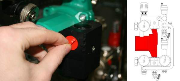
3. Bypass valve (pos. 7 )
During the operation of the heating system, a mode may occur when all the control valves of the underfloor heating are closed. In this case, the pump will work in a damped system (without a coolant flow) and will quickly fail. In order to avoid such modes, there is a bypass valve on the unit, which, when the valves of the underfloor heating system are completely closed, opens an additional bypass and allows the pump to circulate water along a small circuit to idle without loss of performance.

The valve responds to the differential pressure generated by the pump. The differential pressure at which the valve opens is set by turning the regulator. On the side of the valve there is a scale with a value range of 0.2-0.6 bar. The pumps recommended for use with COMBIMIX have a maximum pressure of 0.22 to 0.6 bar.
After the heating system is completely assembled, pressurized with test pressure and filled with water, it should be adjusted. The adjustment of the control unit is carried out in conjunction with the commissioning of the entire heating system. It is best to adjust the assembly before balancing the system.
1. Remove the thermal head ( 1 ) or servo.
To prevent the control valve actuator from affecting the assembly during setup, it must be removed.

2. Set the bypass valve to the maximum position (0.6 bar).
If the bypass valve is triggered while the assembly is being set up, the setting will be incorrect. Therefore, it should be set in a position in which it will not work.

3. Adjust the position of the secondary circuit balancing valve (pos. 2 on the diagram).
The required capacity of the balancing valve can be calculated independently using a simple formula:
![]() t 1
-
the temperature of the coolant in the supply pipe of the primary circuit;
t 1
-
the temperature of the coolant in the supply pipe of the primary circuit;
t 11 - the temperature of the coolant in the supply pipe of the secondary circuit;
t 12 - the temperature of the coolant in the return pipeline (both circuits have the same);
Kv τ - the flow factor of the control valve, 0.9 is assumed for COMBIMIX.
The resulting value Kv set on the valve.

Calculation example
Initial data: design temperature of the supply heat carrier- 90 ° C; design parameters of the underfloor heating contour 45- 35 ° C.
The resulting valueKv
set on the valve.
4. Set the pump to the required speed.
G 2 = 3600 Q / c · ( t 11 - t 12), kg / h;
Δ P n = Δ P s + 1, m water. Art.,
where Q- the sum of the heat output of all loops connected to COMBIMIX; with- heat capacity of the heat carrier (for water - 4.2 kJ / kg · ° С; if a different heat carrier is used, the value should be taken from the data sheet of this fluid); t 11 , t 12 - temperature of the coolant in the supply and return pipelines of the circuit after the COMBIMIX unit. Δ Pс - pressure loss in the calculated floor heating circuit (including collectors). This value can be obtained by doing hydraulic calculation warm floor. For this, you can use the VALTEC.PRG calculation program.
On the nomograms of the pumps presented below, we determine the pump speed. To determine the pump speed, a point with the corresponding head and flow rate is marked on the characteristic. Next, the closest curve above this point is determined, and it will correspond to the required speed.

Example
Initial conditions: underfloor heating with a total power of 10 kW, pressure loss in the most loaded loop of 15 kPa (1.53 m of water column).
Secondary circuit water consumption:
G 2 = 3600Q / c · (t 11 - t 12 ) = 3600 10 / 4.2 (45- 35) = 857 kg / h (0.86m 3 / h).
Pressure loss in the circuits after the unitCOMBIMIXwith a stock of 1 m water. Art .:
Δ Pn= Δ Pwith+ 1 = 1.53 + 1 = 2.53 m water. Art.
Pump speed selected -MEDby point(0.86 m 3 / h; 4.05 m water column):

If it is not possible to calculate the pump, then this stage can be skipped and immediately proceed to the next one. At the same time, set the pump to the minimum position. If during balancing it turns out that there is not enough pump pressure, you need to switch the pump to a higher speed.
5. Balancing the branches of the warm floor.
We close the balancing and shut-off valve of the primary circuit. To do this, flip the valve cover and turn the valve counterclockwise with a hex wrench until it stops.

The task of balancing the underfloor heating branches is reduced to creating the required coolant flow in each branch and, as a result, uniform heating.
The branches are balanced with each other by balancing valves or flow regulators (not included in the COMBIMIX set, flow regulators include the VTc.596.EMNX manifold block). If there is only one contour after COMBIMIX, then nothing needs to be linked.
The balancing stroke is as follows: balancing valves / flow rate regulators on all branches of the underfloor heating open to the maximum, then the branch is selected, in which the deviation of the actual flow rate from the design one is maximum. The valve on this branch closes to the desired flow rate. Thus, it is necessary to adjust all branches of the underfloor heating.
Example
To begin with, we determine the required flow rate of the coolant in the primary circuit. To do this, you can use the following formula:
G 2 = 3600Q / c · (t 1 - t 2 ),
where Q is the sum of the thermal power of all devices connected after COMBIMIX; c - heat capacity of the heat carrier (for water - 4.2 kJ / kg · ° С; if a different heat carrier is used, the value should be taken from the data sheet of this fluid); t 1, t 2 - the temperature of the coolant in the supply and return pipelines of the primary circuit (the temperatures of the coolant in the return pipelines of the primary and secondary pipelines are the same).
For underfloor heating with a total power of 10 kW with a calculated supply temperature of 90 ° C, the calculated parameters of the underfloor heating circuit 45-35 ° C, the flow rate of the heat carrier in the primary circuit will be as follows:
G 2 = 3600Q / c · (t 1 - t 2 ) = 3600 10 / 4.2 (90 - 35) = 155.8 kg / h.
When calculating, the designer determined that the pressure loss across the balancing valve of the unit should be 9 kPa (0.09 bar), so that the flow rate in the primary circuit is 0.159 m 3 / h, k v of the valve should be:
k v = 0.159 / √0.09 = 0.53 m 3 / h.
To determine the number of revolutions, you can skip kv and use the nomogram below. This is done by plotting the required flow through the primary circuit and the required pressure loss across the valve. The closest sloped line will correspond to the required setting (number of revolutions). To improve accuracy, you can interpolate the values obtained.

The first line of the table shows the position, the second line of the table shows the number of turns of the adjusting screw. (In this example, 2 and ¼.) The third line indicates Kv for this setting, as you can see it practically coincides with the calculated one.
Setting the speed on the valve:
Correct setting the valve should go from the position of the valve completely closed, using a thin flat-head screwdriver, tighten the adjusting screw until it stops and put a mark on the valve and on the screwdriver.
 According to the valve setting table, turn the screw by the required number of revolutions. To fix the speed, use the marks on the valve and screwdriver. (according to the example, you need to make 2 and ¼ turns).
 Open the valve up to the stop using the hex key. The valve will open exactly as much as you rotate with the screwdriver. After adjustment, the valve can be opened and closed with a hex key, the flow rate setting will remain the same.
 All other balancing valves in the heating system are calculated in the same way. The number of valve revolutions (or the setting position is determined according to the methods of the balancing valve manufacturers).
The second way of balancing the system consists in the fact that the settings of all valves are set "in place". In this case, the adjustment values are determined on the basis of the actually measured flow rates of the coolant for the hotel branches or systems.
This method is used, as a rule, when setting up large or critical heating systems. During balancing, special devices are used - flow meters, with which you can measure the flow in individual directions without opening the pipeline. Balancing valves with fittings and special pressure gauges for measuring the differential pressure are also often used, by which it is also possible to determine the flow rate in individual sections. The disadvantage of this method is that the instruments designed for measuring the flow rate are too expensive for one-time or infrequent use. For small systems, the cost of the appliances may exceed the cost of the heating system itself.
Before balancing with this method, COMBIMIX is configured as follows:
Fix the flow meter on the pipeline through which COMBIMIX is connected to the heating system. Calibrate and adjust the flow meter according to the instructions for the flow meter.
After that, smoothly open the balancing valve with a hex key, while fixing the change in the flow rate of the coolant. As soon as the flow rate of the coolant corresponds to the project, fix the position of the valve using the adjusting screw.
Example
As in the previous example, the flow rate of the heating medium is first calculated.
For underfloor heating with a total power of 10 kW, the estimated temperature of the supply heat carrier is 90 ° C, the calculated parameters of the underfloor heating circuit are 45-35 ° C, the flow rate of the heat carrier in the primary circuit will be as follows:
G 2 = 3600 Q / s (t 1 - t 2) = 3600 10 / 4.2 (90 - 35) = 155.8 kg / h (0.159 m 3 / h).
Close the balancing valve completely with the hexagon:
 Smoothly open the valve with a hexagon while fixing the flow rate on the flow meter until the flow rate reaches the design one (in the example, 0.159 m 3 / h).
 After the coolant flow is established, - fix the position of the shut-off valve with the adjusting screw (turn the adjusting screw clockwise until it stops).
 Once the adjusting screw is secured, the valve can be opened and closed with a hexagon, without losing the setting.
For small systems
in the absence of a project and complex measuring instruments, the following balancing method is admissible:
In the finished system, the boiler and the central pump (or other source of heat supply) are turned on, then all balancing taps on all heating devices or branches are closed. After that, it is determined heater which is installed farthest from the boiler (heating source). The balancing valve in this device opens completely, after the device is fully warmed up, it is necessary to measure the temperature difference of the coolant before and after the device. Conventionally, it can be assumed that the temperature of the coolant is equal to the temperature of the pipeline. Then we move on to the next heating device and smoothly open the balancing valve until the temperature difference between the direct and return pipelines coincides with the first device. Repeat this operation with all heating devices. When it comes to the COMBIMIX unit, its adjustment should be carried out as follows: If the temperature of the coolant in the supply pipeline is equal to the design temperature, then the balancing valve of the primary circuit should be smoothly opened until the readings on the thermometers of the supply and return pipelines of the secondary circuit become equal to the design ± 5 ° C.
If the temperature of the coolant in the supply pipeline during the commissioning of the system differs from the design one, then the following formula can be used to recalculate:
 where the temperatures with the index "P" -
design, and temperatures with the index "H" -
tuning (used for tuning) values.
where the temperatures with the index "P" -
design, and temperatures with the index "H" -
tuning (used for tuning) values.

Example
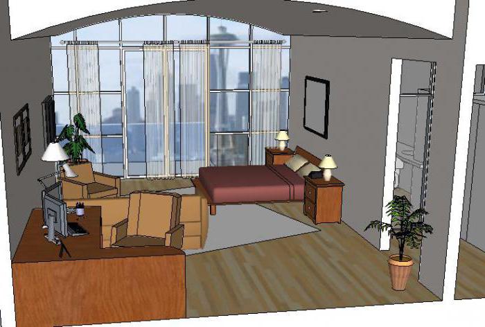
Consider the following heating system:
 To begin with, all balancing valves are closed.
Select the heater that is farthest from the boiler. In this case, this is the right-most radiator. The balancing valve at the radiator opens completely. After the radiator warms up, the temperature of the direct and return pipelines is recorded.
As an example - after opening the valve, the temperature on the supply pipeline was set at 70 ° C, the temperature on the return pipeline was set at 55 ° C.
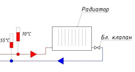 After that, the second device is taken at a distance from the boiler. The balancing valve on this device opens until the temperature in the return pipe is equal to the temperature of the first ± 5 ° C.
 COMBIMIX setting: Calculated flow temperature-
90 ° C; design parameters of the underfloor heating contour-
45-35 ° C. Actual readings taken from thermometers: temperature of the supply heat carrier - 70 ° С.
COMBIMIX setting: Calculated flow temperature-
90 ° C; design parameters of the underfloor heating contour-
45-35 ° C. Actual readings taken from thermometers: temperature of the supply heat carrier - 70 ° С.
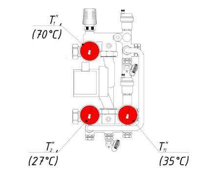 Using the formula, we determine the temperature of the coolant in the supply pipe of the secondary circuit:
 Determine the temperature of the coolant in the return pipe of the secondary circuit:
 We open the balancing valve of the secondary circuit until the temperatures on the thermometersCOMBIMIX
will not coincide with the calculated± 5 ° C.
We open the balancing valve of the secondary circuit until the temperatures on the thermometersCOMBIMIX
will not coincide with the calculated± 5 ° C.
Fix the position of the shut-off valve with the adjusting screw (turn the adjusting screw clockwise until it stops).
 Once the adjusting screw is secured, the valve can be opened and closed with a hexagon, without losing the setting.
 Bypass valve setting
There are two ways to adjust the bypass valve:
2. If the pressure loss on the most loaded branch is unknown, then the setting of the bypass valve can be determined from the pump characteristic.
The valve pressure value is set 5-10% less than the maximum pump pressure at the selected speed. The maximum pump pressure is determined from the pump characteristic.
The bypass valve should open when the pump is close to critical point when there is no water flow and the pump only works to build up pressure. The pressure in this mode can be determined by the characteristic.

Example of determining the setting value of the bypass valve.
 In this example, it can be seen that the pump, in the absence of water movement at the first speed, has a pressure of 3.05 m of water. Art. (0.3 bar) point 1
; at an average speed - 4.5 m water. Art. (0.44 bar) point 2
; and at a maximum of 5.5 m water. Art. (0.54 bar), point 3
.
In this example, it can be seen that the pump, in the absence of water movement at the first speed, has a pressure of 3.05 m of water. Art. (0.3 bar) point 1
; at an average speed - 4.5 m water. Art. (0.44 bar) point 2
; and at a maximum of 5.5 m water. Art. (0.54 bar), point 3
.Since the pump is set to medium speed, we select the setting on the bypass valve 0.44 - 5% = 0.42 bar.
6. The final stage
After adjusting all the organs of the COMBIMIX unit, put back the thermostatic head of the control valve, make sure that the control valve is working. Close the cover of the primary circuit balancing valve. The unit is ready for operation.
Setting up heating systems is one of the most difficult engineering tasks. The VALTEC COMBIMIX pump-mixing unit simplifies this task. This unit is a ready-made complex solution for organizing the underfloor heating circuit in heating systems. A well-thought-out assembly of the unit allows you to eliminate errors in the design of a particular system. The flexibility of setting up the unit allows you to set up underfloor heating systems without the use of special devices.
With the onset of cold weather, the payment for heat increases significantly. With the constant growth of tariffs, this fee is not affordable for everyone. The insulated facade of a house is not always a full-fledged exit. For the correct and accurate regulation of the temperature of the coolant, a special device has been developed that has proven itself well in this area.
The pump-mixing unit not only increases the efficiency of the entire heating system, but also allows you to keep the exact temperature of the heat carrier.
The market for pumping and mixing equipment and auxiliary units is quite saturated. The most well-proven units are manufactured by Valtec, Tim and Rehau. Regardless of the design features, manufacturer and additional functions, the devices prepare the coolant circulating in the heating circuit to a user-specified value. Basically, the values, depending on the environmental conditions, are set from 20 to 60 degrees.
The unconditional appointment also includes:
Structurally, pumping and mixing units are pipeline chains tied together and uniting the primary and secondary circuits. As a result of mixing the heat carrier from the two streams, it is possible to maintain the set temperature value.
Most often, pumping and mixing units are used for the smooth operation of floor heating systems, they heat greenhouses and other objects with water heating.
The use of the device at facilities with increased requirements for the accuracy of the temperature setting and with critical changes in temperature conditions is relevant.
It is quite easy to locate the node in any confined space, since it has a small size. For this purpose, they often equip a special - a manifold cabinet, hiding protruding valve connections and other devices.
To organize the heating of the bathroom floor, room and other premises of the house, the pumping unit is combined with an additional block - a collector. The manifold block acts as a distributor of the contour flows of the warm floor, like a hydraulic arrow.
The branded mixing units of the manufacturing companies are made compatible only with their manifolds, which are supplied with all the necessary connecting elements. For example, the collectors Rehau HKV-D and Rehau HKV are easily connected to the pump-mixing unit PMG 25 from the same Rehau, and Tim and Valtec have their counterparts.
For normal operation, the mixing unit does not require the use of electronic control circuits, and only the circulation pump needs to be electrified. This design makes the device virtually independent from power outages and reduces the likelihood of an emergency stop.
To simplify the organization underfloor heating in everyday life, a special device called a collector is used. This device is a combiner of all linear heating taps, including supply and return. Working in tandem with the mixing unit ensures a comfortable room temperature. The use of the heating medium from the primary circuit is not directly possible due to the very high temperature regime requiring adjustments.
It is important to understand that each brand has its own characteristics in the organization of the nodal block, but the entire assembly, it does not matter Rehau or Tim, does the same job - it provides the supply of the coolant with a given temperature to all supply branches.
The collector unit is two parallel horizontal pipes with connections to the supply and return of the coolant. All details and others structural elements in the bulk are made of:
To control the temperature of the medium and the level of the flow, the supply branch can be equipped with thermostatic valve and the opposite is done with a flow sensor.
The supply valves can provide manual control of the media flow. By turning such a regulator, the operator can manually shut off the heat supply to the branch. The visualization of the flow control for performing actions to hydrobalance the system is provided by flow sensors.
Cheaper manifold block options do not have additional sensors and individualized control options.
Temperature and pressure conditions are monitored by means of the installed thermometer and manometer. The accumulated air in the system is released by a separate valve.
Additional structural elements, sensors and options can be supplied on request or at the discretion of the manufacturer. The Rehau brand has a practice of assembling a complete assembly. Using the example of the PMG-25 pumping and mixing unit of a standard assembly, the kit includes:
Assembled and assembled parts with the use of seals have already been hydro-pressure tested.
A pair of pump-mixing unit and a manifold work according to the following principle. The circulation pump of the unit pushes the coolant along all the branches of the collector. With a drop in temperature indicators below the temperature limit set by the operator, the three- (sometimes two-) -way valve, gradually opening slightly, injects a hot coolant into the line. The resulting excess volume of the coolant flows from the return line to the primary circuit of the general thermal system. Small circuit flow is controlled automatically or manually.
All system failures and malfunctions, such as overpressure, cut off the safety valves or bypasses. Also, other safety measures are not excluded, which are applied until the hydraulic balance of the system is completely restored in order to save the serviceability of the pump and overall performance.
Before the widespread use in everyday life of automatic mixing of flows of the primary and secondary circuits with the help of three- and two-way valves, a device, the so-called hydraulic arrow, was in use.
In the pump-mixing unit, the separation of the coolant into streams is carried out forcibly, the continuity of the flow is divided only due to the movement of water. And the hydraulic arrow has an area with a free zone for mixing water, and the coolant is supplied using its own pump located on each branch.
The pump-mixing unit has instant mixing of two flows of the circuits, and the hydraulic arrow mixes the flows by means of a natural physical process.
It is possible to compare the speed of temperature regulation by two devices by the example of storage and flow-through boilers... But in this case, the flow-through method will also be much more economical than the accumulative one.
Installation of devices should be carried out strictly in accordance with the instructions of the manufacturers.
The inlet and outlet of the primary heating circuit must be fitted with a mixing set or via a heat collector.
The standard connection size with primary leads is 1 inch, and the secondary taps and the manifold are tied with the supplied connectors. The size of the latter may vary depending on the brand model. Seals on the threaded parts of the connectors ensure reliability and speed of installation without additional means (sealants, fum tapes, tow, etc.).
The thermal head must be set manually with the maximum setting values.
The pump for circulation of the heating medium is installed between two valves with a pre-seal.
With the completion of the installation and static checks of the connections, it is time to test the entire heating system. Before energizing the electric pump, make sure that all the locking elements on the path of the carrier are open in order to avoid overloads and emergencies associated with this.
Before the appearance of the pumping and mixing unit, the installation, calculations and adjustment of the heating operation took a lot of time and was very complicated. engineering challenge... Mixing block - ready-made solution tasks of organizing a contoured heating system. By completing the assembly, the user will avoid previous mistakes in the design of the system. And the relatively simple setup eliminates the need for special adjusting devices.
Detailed instructions will help the user to save the payment for the work of the installation organization or to carry out competent control for the acceptance of installation work.