
In the process of designing and manufacturing turning equipment, the master will need the following bench tools:
In the process of designing and assembling the machine, you will need to purchase the following building materials:
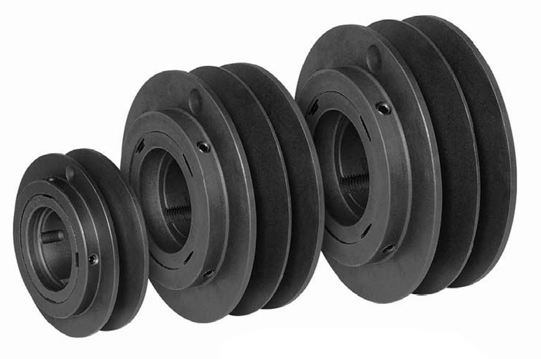
Pulleys provide rotation speeds of 800, 2000 and 3000 rpm
Before you design and assemble a wood lathe with your own hands, you should watch a video on the manufacture of such equipment. Such a video is easy to find on specialized sites dedicated to the manufacture of woodworking equipment.
The use of an electric grinder for the manufacture of the headstock is suitable in all respects - the axis of rotation is high, in addition to this, the unit already has 4 hard alloy washers. Two washers are used to install replaceable discs of different diameters on the shaft of an electric grinder, which are designed to change the rotation speed. On the other side, a special faceplate is made from one of the washers for fixing the blank.
To drive the shaft, pulleys of various diameters are used, providing a rotation speed of 800, 2000 and 3000 rpm. If possible, you can make one combined pulley with different diameter seats for the drive belt.
From an old hand-held electric drill, a cartridge and the front of the body are taken, from which the tailstock is made. When using a part from a hand-held electric drill as a tailstock, you need to choose a drill with a metal case.
To fix the unit, a stand is made, fixed on the machine bed, so that it is possible to move the unit along the longitudinal axis of the machine. The design of the cartridge allows you to exert significant longitudinal loads on it, which is a significant advantage when using it in the design of the device.
The bed is made from pieces of a channel. All elements of the frame are interconnected by using a welding machine. To install an electric grinder that acts as a headstock, a platform made of thick plywood is fixed on the bed.
To fix the lathe, a stand is made
The electric drive of the machine is installed on a special plate fixed on the table, on which the lathe bed is installed. The plate is made in such a way that it can be moved along the direction of the belt. This is necessary to adjust the speed of rotation of the headstock shaft.
A caliper is fixed on the bed with the possibility of its smooth movement along and across the bed. It is made from two pipes of different diameters. A wing nut is used to fix this assembly. A stop bar is fixed on the support, on which cutters for a wood lathe are located in the process of its operation.
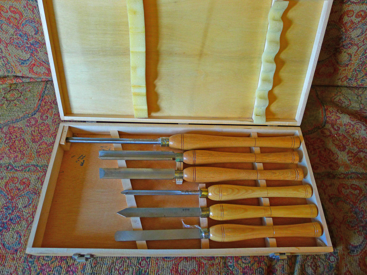
Working tools - cutters for working on a wood turning unit can be made with your own hands, using tool steel plates for this purpose or purchased ready-made in a specialized store. The cost of a set of cutters for working on a lathe ranges from 300 rubles to several thousand rubles. The cost of the set depends on the quality of the incisors and their number in the set.
The cost of a set of cutters for working on a lathe ranges from 300 rubles to several thousand rubles.
After making a wood lathe with your own hands, it is recommended to watch a video on how to work safely and correctly on such equipment. This will allow you to get acquainted not only with the rules for working on this type of equipment, but also to study the safety rules for operating the turning unit.
General instructions for using turning equipment for woodworking include several items that must be followed. The main points to be completed are the following:
The best option for designing a reliable working unit is an integrated approach to the manufacture of each structural element. The frame of the unit should be made especially high quality. This element must provide a high degree of stability during the operation of the equipment. The quality of the functioning of the other components of the equipment also depends on the quality of the manufacture of the frame.
The disadvantage of this type of construction is the high complexity in the implementation of the change in the number of revolutions of the spindle.
The best option for designing a reliable working unit is an integrated approach to the manufacture of each structural element
The choice of the optimal speed of the headstock shaft depends on the size of the workpiece used and the type of wood. To select the required rotation speed, it is recommended to use special tables for the dependence of the rotation frequency on the diameter of the workpiece and wood.
The tree is easy to process. Using simple tools, you can create things of amazing beauty and functionality.
Separately, it is worth noting products that have the shape of figures of rotation: tool handles, stair balusters, kitchen utensils. For their manufacture, an ax or a chisel is not enough, a lathe is needed.
Buying such a device is not a problem, only a good machine is expensive. It is not difficult to acquire such a useful tool and save money, because you can make a wood lathe with your own hands.
The lathe is designed for the manufacture of wooden products having a cylindrical or close to it shape. This is an indispensable thing when repairing a country house with a wooden staircase, a carved porch, but not only.
With some experience, a turning tool will allow you not only to save on purchased decor elements, but also to earn money, because handmade wooden products are highly valued.
Whether such a machine is necessary in a home workshop is up to the master himself.
Of course, if you need several handles for chisels, it’s easier to buy them, but if you want to make an all-wood staircase, then a set of balusters will result in a very large amount. Much cheaper to make them yourself. By the way, you don’t even have to spend money on buying equipment - a simple machine can be made in your own workshop using scrap materials.
The principle of operation of a wood lathe is not particularly difficult. The cylindrical workpiece is fixed along the axis of rotation. Torque is transmitted to it. Bringing various cutters or grinding tools to the workpiece, it is given the desired shape.
The main parts of the lathe:
For ease of use, schemes for changing the rotation speed are used. In professional equipment, this is a real gearbox, a gear system that allows you to adjust the speed over a very wide range. It is difficult, it is enough to equip a home-made wood lathe with a belt drive with several pulleys of different diameters.
Bed - a frame that combines all parts of the machine into a single whole. The strength of the structure as a whole depends on its reliability, therefore the best material for the frame is a steel corner. You can also use a rectangular profile pipe.
First of all, outline the dimensions of the future unit. This indicator largely depends on what kind of products the machine is needed for. The average size of the bed of a home lathe is 80 cm. Using a grinder with a circle for metal, two identical blanks are cut off.
When laying wooden blocks, squares with shelves up and inward, they are laid on a flat surface, their upper edges should create an ideal plane. They maintain the same distance between them, about 5 cm. To orient them correctly, use a rail of appropriate thickness.
The longitudinal details of the base are fixed with clamps. Crossbars are made from the same square. There are three of them. Two are attached to the edges of the structure, the third, which is a support for the headstock, about twenty centimeters from the left edge. The exact dimensions depend on the type of motor used and the parameters of the pulley that could be found.
It remains to weld the frame into a single whole. The seam must be reliable and of high quality, you can cook by hand welding or use an automatic machine.
It is important to immediately decide how the machine will be used. Tabletop installation or stand-alone unit available. In the second option, it is necessary to provide legs. They can be made from the same square, or they can be cut from a bar of suitable thickness. The use of wooden legs will save on material, in addition, the machine can be made collapsible.
The basis of the drive of a lathe is the engine. When choosing this unit, it is important to pay attention to its main characteristic - power. For a home machine, models with power from 1200 to 2000 watts are suitable. The type of connection is important, there are single-phase and three-phase motors.
In a low power desktop lathe, you can use the engine from the washing machine. It is unlikely to cope with the processing of a large workpiece, but it will help to make small decorative elements and kitchen utensils.
There are several ways to transfer rotation to the workpiece. The simplest is direct drive. In this case, the workpiece is mounted directly on the motor shaft. A distinctive feature of this design is simplicity. With all this, direct drive has a number of significant drawbacks.
First of all, a direct drive machine does not allow you to adjust the rotation speed, which is critical when working with hard material. It is also worth considering the load on the electric motor, especially when working with workpieces of large mass. No matter how well it is centered, it will not do without vibration. Motor bearings are not designed for longitudinal loading and will fail frequently.
To protect the engine from breakdowns and provide the ability to adjust the speed of rotation of the workpiece, it is worth considering a belt drive. In this case, the motor is located away from the axis of rotation of the workpiece, and the torque is transmitted through pulleys. Using blocks of pulleys of different diameters, it is easy to change the speed over a fairly wide range.
It is advisable to equip the machine for the home with pulleys with three or more streams, which will allow you to process wood of any species with equal success, and, if necessary, work with soft alloys.
The workpiece to be machined is clamped between two devices called a headstock and a tailstock. The rotation from the engine is transmitted to the front, therefore it is a more complex unit.
Structurally, the headstock of a homemade lathe is a metal U-shaped structure, between the side faces of which a shaft and one or more pulleys are mounted on bearings. The body of this unit can be made of thick steel; bolts of sufficient length are suitable for assembling it into a single whole.
An important part of the headstock, as well as the machine as a whole, is the shaft, a spindle with three or four pins designed to fix the workpiece. This shaft is passed through the bearing of one of the cheeks of the U-shaped housing, then pulleys are mounted on it. For their fastening, a key or a means for fixing cylindrical parts is used, the second cheek is put on last, the structure is securely tightened with bolts.
The task of the tailstock is to support a long workpiece, allowing it to rotate freely. You can buy a finished part of a factory machine, or you can use a chuck of a powerful electric drill, mounted on a square of a suitable length. A shaft with a pointed end is clamped into the cartridge itself.
The front and rear headstock are installed on the bed. It is important to understand that the axes of rotation of both shafts must completely match. Otherwise, a workpiece breakage, machine failure, and possibly an injury to the turner are likely.
Handpiece - a table on which the tool rests during operation. In principle, it can have any configuration, choose the master, the main criterion is convenience. One of the best options for a rest is a trapezoidal turntable made of thick steel, mounted on a platform that allows you to move it in all directions. It will allow you to process any blanks, produce products of various sizes and shapes.
The simplest handpiece for is a square welded to the base. The height of its upper edge should correspond to the level of the headstock axis.
They are used as a cutting tool for a lathe. You can buy a similar tool in almost any hardware store. Individual cutters and whole sets are available for sale.
If there is no store nearby, but there is an opportunity and desire, you can make the necessary tool yourself. To do this, you need a metal-cutting machine, as well as a tool steel blade, it can be replaced with an old tool. A high quality turning tool can be obtained, for example, from an old Soviet file.
Often there is a need to turn a few small wooden parts, in this case it is not at all necessary to make a full-fledged machine, you can get by with a mini-turning machine for wood. Its manufacture does not require much labor and does not take much time.
The device of such a machine is extremely simple. As an electrical component, an engine from an old tape recorder, powered by an external power supply, is perfect. The bed of the mini-machine will be a piece of board of the required length.
The engine must be secured. Of course, a belt drive is not suitable for a small machine, the workpiece will have to be mounted on the motor shaft. The best tool for this is a faceplate. The drive housing is a U-shaped plate, in the center of which a hole for the shaft is drilled. The engine in the housing is mounted on the bed with the help of self-tapping screws.
The main part of the machine is ready, it remains only to make the tailstock. Its body is made from a bar of a suitable size. A hole for the shaft is drilled in it exactly at the height of the engine; a dowel-nail of a suitable length is used as it. The headstock is attached with glue and a few self-tapping screws.
Using a power supply with adjustable output voltage, you can create a machine with a variable speed of rotation. It is convenient to regulate the speed using the foot control pedal. The design of this device can be very diverse, it all depends on the available parts.
Perhaps every home master has such a useful thing as an electric drill. This is a truly versatile tool, they are used for drilling, mixing mortar, cleaning surfaces. Not surprisingly, many people have the idea of using a drill motor to make a small wood lathe.
This is not difficult. By and large, it is enough to fix the drill on the frame, and install the tailstock opposite it, it must be movable, which will allow you to adjust the working distance.
There are many options for manufacturing such a lathe, they differ in complexity, the materials used. In the simplest case, the machine is a board or a piece of thick plywood, at one end of which there is an emphasis for a drill with a lock, at the other - a rear beam: a bar with a shaft inside. As a shaft, you can use a sharpened screw or dowel of a suitable diameter.
If you have the skills to work with metal, you can create a machine of just the same professional level. Using it, it is easy to produce products of the highest class. If the machine is needed from time to time, the best option is a drill machine. If necessary, you can grind the required part, and if you need a drill, it can also be used for its intended purpose.
The first machine that every artisan feels the need for is a desktop drilling machine, or simply a drill. But upon purchasing it or making it with your own hands, it soon turns out that you need to sharpen something, and a lathe costs an order of magnitude more expensive. Great is the temptation to make a universal lathe like the one in fig. below:

Before the ingenuity, skill and accuracy of such masters, it remains only to take off your hat. Yes, wood can also be turned on a metal lathe; many of these bench lathes are equipped with inserts in the spindle chuck to hold the wood workpiece. But - alas! - a home-made universal lathe will not hold accuracy on metal for a long time.
The point is not only that the cutting force of metal is many times greater than that of wood. The very physics of metal cutting is completely different. In order not to go into the basics, even a cursory superficial review of which will require an exorbitant amount of space, let's take it and compare it: have you seen a metal cutter, sharp as a chisel or a piece of iron planer? And what happens if you cut a tree with a chisel? The drill can still cope with both materials: there the cutting force is symmetrically concentrated on the working body itself. But as far as the point of metal is concerned, the requirements for the machine tool, the requirements for the machine tool for it, turn out to be such that machine tool building became a separate branch long before the industrial era. The best machine-building plant does not make machine tools for itself - it is not up to it. However, it is quite possible to assemble a wood lathe with your own hands, and in such a way that it will keep the maximum machining accuracy of +/-0.5 mm achievable on wood for many years, if not decades. You still cannot do without 2-3 turning operations for metal (see below), but in this case they can be performed to order by a turner of 2-3 categories on a conventional, not increased accuracy, machine, even if it is a restored DIP. And, of course, you will need to buy a set of cutters for processing wood on a lathe, see Fig. Everything else will not require mandatory additional costs.

Further in the text, you will come across technical solutions that are effective, but little known to amateur craftsmen, because. in industry, for one reason or another, they are not used or are used to a limited extent. However, they can simplify and facilitate the manufacture of a home-made lathe for woodworking so much that in some cases it will be possible to limit oneself to a hand drill from a power tool. The machine tool industry of the millennium is developing under the sign of solving the problem: how to make machine parts with an accuracy of, say, 0.2 of the same units on a machine tool with an accuracy of, for example, 1 conventional unit of length? Etc. In order to understand how technology came to such a life, it will be useful to turn briefly to history.
The progenitor of all machines for processing materials by rotation is a device with which Neolithic people made fire and drilled horn, bone, stone, pos. 1 in pic; in the latter cases, an abrasive of wet quartz sand was sprinkled under a drill made of wood or bone. The primitive Celts, on the same principle, came up with a foot-operated lathe, pos. 2; the centers were made of sharpened burnt stakes of hard wood. In England, this unit is still in use among furniture makers. The forest is not cut down there by quarters. Having bought a couple of timbers for felling, the master then takes out ready-made legs, balusters, etc. in armfuls to the track. In a craft of this type, the machine lived approx. until the beginning of the 18th century, pos. 3, although the workpiece in it rotates back and forth and the master has to be additionally distracted to turn the cutter over.

In ancient Egypt, already in the era of the Middle Kingdom, a lathe with a beam drive was well known, pos. 4. "Motor" was, of course, a slave. In the Russian village community (in the world), with its strong traditions of mutual assistance and mutual assistance, the beam lathe survived in the outback until ... the 80s of the last century! Mass individual wooden construction was in no way included in the plans of the five-year plans, but the Soviet leadership in the provinces turned a blind eye to unauthorized logging on a limited scale for their own needs or to the unauthorized purchase of wild logs from timber industry enterprises for the universal Soviet currency with a strength of 40 vol. and half a litre.
For fine and / or fine work, a foot loom with twine and bow was not suitable: there are always inhomogeneities in the tree, and the workpiece itself was the flywheel - the damper of torsional vibrations. Radical improvements to the lathe were introduced by the master Theodore in Ancient Greece approx. in 400 BC uh, pos. 6. He supplemented the foot drive, firstly, with a crank - now the workpiece rotated in one direction. Secondly, I made the centers rotating and provided one of them with a grip to hold the workpiece. Thirdly, he introduced a heavy flywheel into the kinematic scheme. Separate machines of this design were in operation at industrial enterprises before the start of the electrification of industry, pos. 7 - in the then complete absence of social guarantees, the labor of an unskilled helper was cheaper than the cost of maintaining a steam engine.
The electrified wood lathe (item 8 in the previous figure) has not changed much since the end of the 19th century (see also the figure below):

A non-volatile wood lathe may still come in handy these days; say, in a country house or an unequipped construction site. The muscular strength of a normally developed person is sufficient for turning workpieces from ordinary timber with a diameter of approx. up to 150 mm. In such a case, 2 options are possible (see the following figure): a good old machine with a foot drive (the dimensions of its most important unit - the crank are given at the top right); for more on it, see below, and processing on a goat with a manual drive towline (lower right in the figure). Lesina in girth cannot be rounded in this way, but it is possible to machine the supporting pillars of the porch, gazebo or canopy over the barbecue.

The first question that needs to be addressed is: since certain obligatory costs (see below) are inevitable, is it possible to purchase a woodworking machine without getting into a loan and without cutting the budget? There are, and very good ones.

If you come across an old UBDN-1 at a reasonable price (on the left in the figure) or its modern counterparts (in the center), do not yawn! There is no need to re-equip anything at home: a motor up to 350 W with double insulation of the windings. The machine is plugged into a regular socket, grounding is not required. And you get in one product:
Another option, most likely cheaper, but only for horizontal drilling and turning - a drill frame that turns it into a lathe, on the right in fig. The beds of drills for a drill are already being sold almost on the streets peddling, but far from everyone knows about turning. Meanwhile, an electric drill as a machine drive for wood has serious advantages (see below), and a lathe with it will be no worse than a branded one. But much cheaper.
Note: for starters, it’s better to whip up a simple lathe and work on it a little. Wood turning skills are easy to develop, and how to quickly make a simple wood lathe, see the video:
The next question is what to make a homemade lathe from? The answer seems to be obvious: from metal, after all, there cannot be a machine weaker than a workpiece, can it? And how did primitive people drill stone with wood? How did the ancient Egyptians build pyramids with wood and copper (there was no bronze then)? And see above about the main issue of machine tool building.
A lathe for woodworking can be made of metal (pos. 1 in the figure), metal-wood, pos. 2, from improvised materials with minimal use of metal, pos. 3 and even ... without a frame, pos. 4. So, on any of them, a fairly experienced and accurate craftsman can work regularly for a long time with maximum accuracy for a tree. Wood is not only a noble, but also a grateful material.
Yes, but which tree to take? Best of all - oak without defects, seasoned, having undergone complete natural shrinkage and shrinkage. Lathes made of quality oak 100 or more years old still work today. And as for home-made work - the frame and headstock of an oak (in the literal sense) machine are made very simply, see below.
If there is no oak lumber of suitable quality, then you can get by with ordinary drill pine, but the bed will have to be made according to the frame-and-beam power scheme. In Anglo-Saxon countries, where oaks have long been registered individually, such home lathes are very common. Drawings of an "English" wood lathe with a frame made of ordinary timber are given in fig; dimensions in inches. This is actually an ancient foot machine with a crank, adapted for an electric drive. To return it to a non-volatile form, it is enough to extend the middle rack of the bed to the bottom, put it on the paw and mount the pedal with the connecting rod, crank and flywheel, see above.

Working with a muscle motor is, of course, an amateur: now electricity is available almost everywhere. In extreme cases, you can also be powered from the car battery through a voltage converter. If you meet somewhere in other articles on this topic something like: pull a 3-phase cable towards you, make a protective ground, buy a 3-5 kW motor, do not believe the elephant that he is a buffalo. To round a wood of medium "clumsiness" up to a diameter of 300 mm, a machine drive power of 1-1.5 kW is sufficient; for turning a 200 mm log into a figured support post - 350 W.
Much more important is the spindle speed. The frequency of its rotation should not exceed 600-700 rpm, otherwise the probability of “biting” the cutter and the occurrence of a traumatic situation increases sharply. It is best to limit yourself to speeds set within (60-70) - (300-400) 1 / min. Then the following is possible. drive options:
It is not easy, because it is impossible to regulate the rotation speed of an asynchronous electric motor by changing the supply voltage: the slip of the rotor grows like an avalanche and, accordingly. torque drops. Making a powerful frequency converter is difficult and expensive. It remains only 2-3 speed manual transmission. Belt or chain - they dampen jerks due to inhomogeneities of the workpiece, and gear, on the contrary, enhances them. Plus - a heavy rotor, heavy pulleys, an elastic belt. The inertia of the torsion drive turns out to be such that it is possible to sharpen completely knotty blocks of a shape on a cut that has nothing in common with a circle. Minus - you need to order or look for turned pulleys.
The speed of rotation of an asynchronous electric motor can be changed in steps by switching the windings. Motors of this type are installed in some models of washing machines (only in washing machines with a direct drum drive) and in floor fans with airflow switching. The rotation speeds in both cases are ideal for woodturning. Fan motor power approx. 40-70 W, which is enough for a mini-machine (see below). The motor power from the washing machine is 300-400 W - quite enough.
Drawings of a wood lathe with a motor from a washing machine are shown in Fig.:

A motor from a washing machine with a direct drum drive as a drive for a woodworking lathe has a great advantage: its bearing assemblies are designed for a large unbalanced load, so it will be possible to sharpen the most viscous and serrated wood. But with knots, the situation is worse: the flywheel is only the rotor of the motor, and the cutter will twitch on them.
Note: how to make a wood lathe with a motor from a washing machine, see video:

From the point of view of an ordinary home craftsman, both machines have a big drawback: you need to either put a grip on the headstock only for wood, or order an adapter for the motor shaft with a Morse taper for a clamping cam chuck. Finding the sizes of typical Morse cones on the Internet is not difficult; the dimensions of the cone for a conventional drill chuck No. 1, see fig. on right. But - you need to sharpen the cone with an accuracy of no worse than +/-0.025 mm. That is, you need a metal lathe with increased accuracy of 0.02 mm. A master of sufficient qualification who owns such equipment may simply not be found within reach.
If the drive of the machine is an electric drill, the problems of precision processing disappear: the cartridge can be removed with a home-made puller, and a typical purchased holder for a wooden workpiece can be placed on the cone. Or just clamp the same chuck, but cheaper with a cylindrical shank. Or even make a workpiece holder yourself, (see below).
The design of such a critical unit as the headstock in a lathe from a drill is also extremely simplified: it turns into a simple clamp. Two options for drawings of a clamp for a drill for a lathe are given in fig:

Headstocks - clamps for a wood lathe from a drill
Left metal; on the right - from solid small-layer wood. Wooden is better: it dampens vibrations well and does not spoil the collar of the drill. Its manufacture has some peculiarities:
An electric drill as a machine drive has only one drawback: a commutator motor with a thyristor speed controller. At a low speed, the torque on the shaft drops noticeably, this is already felt when drilling. Therefore, on a machine from a drill with a power of 280-350 W, it is possible to sharpen wooden blanks with a diameter of approx. up to 150 mm. However, the simplification of the manufacturing technology of a woodworking lathe driven by a drill is so thorough that drill machines are made in a wide variety of versions, see a selection of videos:
From improvised materials without a bed:
With plywood frame:
Regular design:
Improved with extended functionality:
The metal and oak bed of a wood lathe have their own advantages and disadvantages. But by combining wooden power (bearing) elements with reinforced metal fasteners, it is possible to get a frame that is made “on the knee” with a hand tool + an electric drill and will last at least 20-30 years.
The design of the combined frame of a wood lathe is shown in the figure:

The main structural material is a standard oak beam 100x100 3 m long. The overall length of the frame is 1.2 m. The drawing is to scale, the missing dimensions can be removed and recalculated in mm from it. If there is more good oak, the length of the bed can be increased to 1.5-2 m. Both headstocks are of the same design and are designed for home-made rotation units, see below. The ridges at the bottom of the pasterns eliminate the skew of the centers. The whole structure can be made with hand carpentry tools and an electric drill.
Note: a mini-lathe for wood was made according to a fundamentally the same power circuit, see next. rice. It will fit a motor from a 2-3 speed floor fan, see above, with a 1: 1 gear.
The totality of the qualities of an oak bed is quite enough for turning wood. The use of metal for this purpose in mass production is dictated by economic considerations: it is simply that the cost of a metal product intended for continuous 3-shift operation turns out to be much less than a wooden one. 1 cu. m of aged oak is much more expensive than a centner of conventional structural steel.
Amateur craftsmen, not knowing about it, often “for the sake of strength” make the beds of lathes for wood from a channel. But it turns out rough even for “wooden” accuracy (on the left in the figure), and trimming the working surfaces of channels at home is not realistic. In addition, welding can lead the entire structure with a “propeller”, which is completely unrealistic to fix. Therefore, it is better to assemble the frame from the channel with bolts (on the right in the figure).

Much more reliable in this regard is the frame of twin pipes (on the left in the next figure): when welding, it leads less, you can correct the skew by pulling the frame with bolts to the base, and it is possible to achieve a divergence of the centers of handicraft headstocks of 0.2 mm or less . Drawings of a welded tubular bed of a lathe for wood from a drill are also shown in fig.

It would seem that it is impossible to make the headstock of a lathe, and the back one with a rotating center, without precision turning work. No, it is possible - using the phenomenon of oil hydrodynamic cushion (OHD). This, by the way, is one of the ways to answer the question: how to make parts for a machine with an accuracy of 0.2 on a machine with an accuracy of 1. In mechanical engineering, the GDP is rarely used, because. for its formation and stabilization, the machine with the workpiece fixed in it must idle for 2-5 minutes. If a shift lesson is only 10 parts, then every shift loss of working time will be up to an hour or half an hour, which in mass production "rolls over". But in general, in the GDP technique, it is not uncommon. For example, warming up the internal combustion engine of your car is necessary incl. and in order to form a GDP between the connecting rod clamps and the crankshaft journals, otherwise the motor resource is sharply reduced.
The principle of operation of the GDP is shown in Fig.:

Any grease is suitable for it: grease, grease, cyatim, fiol. But best of all - shahtol, special lubricant for mining machines and mechanisms. Due to the difficult working conditions, they, like the Kalashnikov assault rifle, are made with large gaps between the rubbing parts, but they are not required to fire quickly. Shaftol is specially designed for relatively slow moving joints of rotation and is excellent for wood lathe headstocks using HDF.
The device of a typical headstock of a lathe for woodworking is given on the left in fig. There are so many metal lathes in it for an amateur, and the shaft journals and bearing cap sockets need to be sharpened with the same accuracy as the Morse taper.

For a home-made headstock using the GDP, you will need, in addition to purchased threaded parts: M12-M20 studs for the shaft, nuts and washers for them, another piece of bronze (not brass!) Foil 0.2-0.35 mm thick and, on the clip, steel tube with walls of sufficient thickness (see right in the figure). The entire assembly is made next. way:
If you don’t trust any very smart physics there (although nodes with GFS keep accuracy no worse than analogues on rolling friction), then in fig. - drawings of a bearing assembly, equally suitable for a homemade circular saw and a wood lathe. In the latter case, a flat sole with side supports is not needed - the round body is simply inserted into the headstock body and fixed with a screw. Instead of a saw blade, they put either a faceplate or an adapter with a cone for a chuck (det. 6).


The designs of the rotating centers of lathes for metal (at the top in the figure on the right) and for wood (in the same place below) are not fundamentally different, only the “wooden” one is designed for many times lower loads. But in work, especially at home, there is a significant difference: axial holes in turned wooden parts are drilled extremely rarely, because. their strength is greatly reduced by this - wood, unlike metal, cracks easily. That is, by abandoning the quills for interchangeable working bodies, it is possible to simplify the design of the tailstock to suitability for manufacturing “on the knee” with a small share of simple custom-made turning work.
A typical design of the tailstock of a wood lathe is shown in fig. below. On the right there is an insert with a rotating center in a wooden tailstock made from a garage door hinge. It also uses the GDP, and the center shank is fitted to the cage in the same way as the headstock shaft, but simpler and lighter: the gap between the pin and the socket of the garage hinge is approx. 0.5 mm and, as a rule, the assembly turns out to be suitable for work without fitting and grinding.

Some difficulties are caused only by fixing the center from the reverse longitudinal stroke. It is unrealistic to cut a trapezoidal thread and make a lock cracker or an eccentric for it at home, and the lock screw will quickly crush the usual metric thread. The output is a floating aluminum sleeve. Locksmiths are familiar with this method: if you need to clamp a threaded part in a vice, they wrap it in thin aluminum or put it between aluminum spacers - absolutely nothing happens to the thread.

The simplest tool holder for a cutter is a piece of board with a wooden boss nailed / screwed to it. But this is not suitable for fine work: during the point of shaped parts, you need to turn the shelf (stop) of the cutter, without loosening the fastening of the handpiece itself and without moving it. Therefore, the handpiece must be made of metal with a swivel stop, however, custom turning and milling work is not required for this; see drawings in fig. on right.
So we got to the last question: how to securely fix the workpiece in the headstock of a woodworking lathe? Considering that the tree is easily torn, crushed, pricked, and the blocks on the lathe sometimes come in forms that are simply amazing.
The answer to this question is not as terrible as the devil is painted. Universal holder - trident, pos. 1 in fig. It is these that are supplied with household woodworking machines, for example. mentioned UBDN-1. The shank is either smooth for a chuck or threaded for mounting on a shaft. The trident holder securely holds workpieces up to 100-120 mm in diameter, and round ones up to 200 mm. There is only one drawback: it is very difficult to make a good trident for a wood lathe.

Screw chuck for small clean work (for example, turning wooden glasses), pos. 2, it is generally impossible to do without special equipment, but it is successfully replaced by a clamping chuck, pos. 3. If you need to process, on the contrary, a large workpiece with an irregular configuration in the cut, use a faceplate, pos. 4.
A faceplate for turning wood can also be made independently from bakelized plywood with a thickness of 12-16 mm. In this case, the washer is made 2-layer: the same one made of sheet steel 1-1.5 mm thick is attached to the plywood circle on the back side. Holes for spikes in a plywood circle are drilled through, and instead of turned spikes, then you can put cut-off nail tips. A glass for installing a faceplate under a nut on a threaded shaft shank can also be made from plywood rings and a steel bottom.
Finally, on the basis of a 3-4 layer faceplate, you can make a homemade cam chuck for wood, pos. 5. Are the cams sure not to converge? So the accuracy of the workpiece is even worse. But you can sharpen bowls, saucers, etc. from cuts of a valuable tree. products that do not leave traces of processing.
Note: the variety of wood blank holders is not limited to those described. For example, see the video on how to make a mini lathe with a hole holder for the smallest woodwork:
Making a machine and working on it are different things not only in industry. Therefore, in the end, see a selection of videos on how to sharpen a tree on a machine and make a copy machine for wood for turning balusters out of a grinder.
From time immemorial, the tree faithfully served people. Wood is the subject of labor for a master carpenter. Particularly popular are things made on a lathe. Many metal turners like to sharpen wood. The ability to work on metal-cutting equipment motivates them to make a wood lathe with their own hands for their home workshop.
The woodworking equipment market has a wide range of wood lathes. Each consumer makes his choice taking into account his interests, but the main criterion is the drive power. For a home workshop where turning work is performed sporadically, a simple desktop machine with a 1 kilowatt electric motor and a spindle speed of 3500 rpm is suitable.
The main components and mechanisms of the woodworking machine correspond to the classical device of a lathe that processes workpieces by rotation. Three main mechanisms:

Four main knots:
 A do-it-yourself wood lathe can be assembled from improvised material. The design is simple, it does not take much time to manufacture. The main part of the machine is a frame made of a channel, in which a groove is cut along the central axial line by a grinder for fixing the handpiece and the tailstock. The principle of fixation is an eccentric mechanism.
The design of the tailstock is standard. The quill has a hole for Morse taper No. 2 for setting the center of rotation. The shank of the drill chuck matches the hole of the quill. It is recommended to use a factory-made tailstock.
If a homemade wood lathe is designed for turning and drilling parts without precision requirements, you can make it yourself.

Under the quill, turn a hollow cylinder with a blank end wall, in which a thread is cut for the flywheel screw. The movable part of the quill is a cylinder with a conical bore and a full length keyway. The movable part moves with the help of a flywheel screw along a key welded in the headstock housing.
The hand rest is classic, has the function of regulation with fixation to the diameter of the workpiece being processed, the base of the hand rest moves across and along the bed. It is fixed with an eccentric with a handle. The upper part is the usual corner.
Two angular contact bearings are installed in the headstock. The spindle shaft is threaded M14, step two. This is a thread that is used on grinders, grinders. Thanks to this, all nozzles that are used by the grinder can be attached to the spindle.
With this thread, a faceplate was made for a lathe chuck. This whole structure is rotated by an electric motor from a 300-watt washing machine.
 The quality of the entire structure depends on the accuracy of the manufacture of the headstock. Therefore, special attention must be paid to this node. Craftsmen recommend making the headstock of a lathe with their own hands. To do this, you need to machine a cylindrical body with a wall thickness of 10 mm. For fastening to the bed, you need to make a special rack. For this, a section of the channel is suitable. The channel end is welded to a corner made of sheet steel 10 mm thick. The body of the headstock is attached to the resulting rack.
To make a wood lathe with your own hands, drawings and dimensions do not matter, since everyone makes the design individually, taking into account their capabilities. Cylindrical body in section:

Simple fixtures make the machine versatile and increase the list of operations. For example, by installing a grinding drum with sandpaper in a chuck, you can sharpen a tool. The copier turning device looks like this:
The milling attachment will replace the milling machine. Arbor with disc cutter

clamped into a cartridge. Instead of a handpiece, a desktop with a persistent ruler is installed. It is possible to mill platbands, skirting boards, blanks for frames.
Enthusiasts and lovers of making homemade products are constantly coming up with mechanisms that facilitate manual labor. Such people always have an answer to the question of how to make a woodworking machine.
Craftsmen manage to make a homemade small lathe for wood, spending 30 minutes of time. The material for the manufacture of chipboard with a thickness of 20 millimeters or thick-layer plywood. The device has such a scheme:
 The tailstock is made of two rectangular bars assembled into a structure at right angles. A mounting hole for an electric drill is drilled in the rack, a latch is made for reliable fastening. The stand is fixed to the base. A hole for a screw is drilled in the tailstock, the end of which is sharpened to a cone. This is a hard center. The improvised tailstock moves along the guide slot, is fixed in one turn of the eccentric. The armrest is made of a rail attached to the base.
Such a simple homemade product will make it possible to easily carve a handle to a file or a rocking shaft for dough out of wood. And in general, woodworking is a very interesting activity.
Any workshop owner, even if it does not have a separate room and is simply organized in a garage, strives to equip it with everything necessary for comfortable, productive and, most importantly, high-quality work. That's just on a hand tool in our time, you can’t “leave” far. A great variety of power tools, various multifunctional or narrow-profile machines, and auxiliary equipment come to the rescue. There are no problems with the offer - the main difficulty is that high-quality products cost a lot of money, and not everyone can afford it.
But craftsmen find a way out by making such machines and devices on their own, some of which may well compete with factory models. Moreover, to create such equipment, quite affordable materials are used, often just gathering dust in the barn. And as drives, running power tools are widely used, usually available in any workshop.
In this publication, only some home-made machines and fixtures for the home workshop will be considered. It should be correctly understood that it is simply impossible to cover all the available variety of such equipment within the framework of one article. Here it is just right to allot such a topic in general a separate site. So basically a general overview will be given. But the manufacture of two models, which are very important, probably, for any workshop - a pendulum saw and a sharpening machine for cutting tools, we will consider step by step, with all the nuances, from the first sketches to testing.
The comfort of working in the workshop depends on many important conditions. If we take out the issues of heating, ventilation and lighting (these are topics for separate consideration), then the rational, convenient organization of the main workplace always comes to the fore.
We are talking about a workbench and a well-thought-out storage system for the tools, accessories, consumables and other small things necessary for work.
The workbench is selected or manufactured independently, depending on the main direction of work in the workshop.
If the owner is more focused on woodworking, then he will need a carpentry workbench. There is a long used and comprehensively tested general concept of such a workplace. Probably, it makes sense to stick to it when making a workbench on your own.

The workbench is based on powerful wooden legs (pos. 1), which from below, at the base, are usually connected in pairs with lintel supports (pos. 2). There is a lid on top - a workbench (pos. 3). As a rule, a recessed area is provided - the so-called tray (pos. 4), so that during the work the tools or components necessary at hand do not fall to the floor.
Usually on the right side there is a side or rear clamp (pos. 5). In fact, this is a screw vice, in which a wedge is provided (pos. 6) that extends upwards. Along the line of this wedge along the bench there is a row of sockets (pos. 7) for similar wedges (they can be hidden in these sockets or stored separately and inserted as needed). This allows you to rigidly fix the wooden workpiece for processing between the wedges of the table and the side vise.
To fix a long piece that cannot be secured between the end wedges, use the front clamp (pos. 8). This is also a screw vice that is able to clamp the workpiece between the front end of the workbench and a movable wooden sponge. And in order for the long part to have the necessary support points from below, the fingers hidden there in the grooves or retractable supports (pos. 9) extend from the end of the workbench.
The lower area of the workbench is called the workbench (pos. 10). As a rule, powerful crossbeams (prolegs) are located here, connecting the legs in pairs, imposition in the longitudinal direction. On these crossbars, shelves are often organized for storing tools or workpieces, or even, as shown in the diagram shown, a closed cabinet.
Below is a drawing of a workbench. Anyone who can read diagrams and has carpentry skills will be able to make such a model on their own.
To begin with - a general wiring diagram of a carpentry workbench with dimensions.

Now - a series of drawings for individual parts and components of the structure.
As a rule, high-quality coniferous wood with a residual moisture content of not more than 12% is used for the manufacture of parts for the underlay (base).


The workbench (cover) is mainly made of hardwood - it can be beech or oak, ash or maple. To make such a massive overall panel on your own is an extremely difficult task, therefore, a ready-made glued shield is often ordered or purchased in a carpentry workshop. It is unlikely that this will seem like a too expensive solution, given both the cost of the material and the laboriousness of the process. So it is more profitable to purchase a finished product, and then modify it for a workbench.
By the way, when performing various processing operations, one way or another, the surface of the desktop will be damaged. To maximize the life of the workbench, the lid is often covered with a plywood or fiberboard sheet (naturally, according to the size of the table and with all the necessary grooves and sockets). As such a coating wears out, it can be replaced with a new one - this is not so difficult and inexpensive.

Particular difficulty is usually attached to the installation of the front and rear (side) clamps. In order to get really workable and convenient devices, it is better to purchase the screw vice mechanism itself in a finished, assembled form. There are many models available for this purpose.

To assemble these clamping units, you can refer to the following drawing:

The vise jaws must be made exclusively from hardwood, the dimensions and location of the holes are shown on the drawing. (It should be correctly understood that the location and diameter of the holes must correspond to the purchased screw mechanism).

And finally, the last diagram shows how to attach the rear fixed jaws of both vices to the workbench cover.

Of course, an example is shown here, moreover, it can suit many in its “pure form”, that is, without changes. But if other dimensions are required (based, for example, on the available space), then you can draw up your own drawing by taking the demonstrated diagrams as a model for assembling certain nodes. The principle still remains the same. If necessary, no one bothers to make their own improvements, which, of course, should not adversely affect the strength of the structure.
If the master plans to mainly engage in locksmith operations, then he will need a completely different workbench, designed specifically for such purposes. Here, in contrast to the carpentry "classics" - an innumerable number of possible options. as a rule, steel profiles (corners, channels, profile pipes) and sheets are used for manufacturing. One of the quite worthy options is shown in the video below:
An important component of working comfort in the workshop is always the optimized arrangement and storage of tools and accessories. But we will not dwell on this, since a separate article is devoted to this topic on the pages of our portal.
How to make the workshop as comfortable as possible for work?
It is convenient when you know where everything is and when the necessary tool is always at hand. So you should pay close attention to the system of cabinets, racks, cabinets, reasonably organized places for storing consumables. This is especially important in cases where the size of the room does not allow "roaming". Questions on our portal have a special publication.
As already mentioned, the variety of home-made machines is extremely large, and it is simply impossible to tell about all of them. Therefore, in this section of the article, the reader will be offered several video reviews. And, in addition, in detail, the manufacture of two models of machine tools will be considered step by step.
In the economy, it often becomes necessary to carve one or another wooden part of a circular cross section. If you do not do this professionally, then acquiring a real lathe is completely unprofitable. And yes, it will take up a lot of space. But to have at your disposal a miniature machine that can be stored in a closet and assembled as needed - never hurts. Moreover, its manufacture is not so difficult.
This can be seen by watching the proposed video. Despite the fact that the author speaks English, all his actions are shown in detail and are quite understandable. And such a machine, guided by this video hint, is within the power of everyone to do.
If it becomes necessary to harvest a considerable number of wooden parts of the same size, then nothing better than a stationary circular saw can be invented. And it is quite possible to make such a machine, and, again, in a collapsible version, which, out of uselessness, does not take up almost any space at all.
It will take only a sheet of plywood, a few bars and self-tapping screws. And the main element of the design becomes a hand-held vertical saw
In the plot shown, the master removes part of the protective fence of the manual circular. This is not always necessary. It is quite possible that the free exit of the saw will be enough if it is intended to cut not too thick workpieces.
When cutting blanks or wood or metal, including shaped or round pipes, high accuracy is often required. Moreover, the accuracy is not only in linear dimensions, but also in the magnitude of the cut angle. A typical example is when it is necessary to accurately cut workpieces for a frame in which the joining of parts is either strictly perpendicular or at an angle of 45 degrees.

A pendulum saw allows you to perform such an operation. The diagram above shows in a simplified form the principle of its design and operation.
In any case, there is a reliable base (bed, frame) that ensures the stability of the machine (pos. 1). In many models, a desktop is organized on top of the bed with a system of guides, stops and clamps that allow you to accurately set the workpiece to be processed. There must be a slot (pos. 2), exactly into which the rotating circle or saw falls.
The support (pos. 3) of the oscillating part of the machine is rigidly attached to the frame. It is equipped with a block of bearings and an axle (pos. 4), relative to which the swinging rocker platform (pos. 5) rotates. An electric drive (pos. 6) is placed on this platform, which transmits rotation directly or through a transmission system (pos. 7) to a cutting tool - a cutting wheel or a circular saw (pos. 8). A lever (pos. 9) or a handle is provided, with which the master can smoothly lower the cutting disc down onto the workpiece fixed on the work table above the slot.
But the possibilities of this tool will become immeasurably wider if a special milling table is made for it. One of the options for such a home-made machine is in the proposed video.
And in the workshop, and in the kitchen, and just around the house, a lot of cutting tools are used that need regular sharpening. Running disc sharpeners for knives give a very short effect of the sharpness of the cutting edge, as they remove metal along the edge of the blade, and according to all the canons it is required - perpendicular to it. When sharpening manually with the help of bars or on a rotating sharpener, it is very difficult to accurately maintain the optimal angle, especially if it is equal along the entire length of the blade. By the way, this full sharpening angle is different for different types of cutting tools - there are many separate publications on the Internet on this topic.
This means that in order to sharpen, for example, a knife, a device is required that would allow applying a force with the translational direction of the flat abrasive perpendicular to the cutting edge consistently along its entire length with a single, pre-inserted angle of inclination. And to provide visual control over the course of formation and sharpening of this cutting edge.

There are many such devices on the market. But if there is a desire, then a similar machine can be made independently, using materials that may be found in a workshop or garage. Yes, if you buy what you need, it will come out quite inexpensively. An example is shown step by step in the table below.
| Illustration | Brief description of the operation to be performed |
|---|---|
 | The entire design of the machine, all its parts and assemblies will be somehow mounted on the base - the bed (frame). For its manufacture, a profile pipe of square section 20 × 20 mm is well suited ... |
 | ... with a wall thickness of 2 mm. As it will be clear further, there are no strict proportions of sizes - they proceed from considerations of common sense, the strength of the structure being created, the presence of certain materials. |
 | Blanks for the frame are cut from the profile pipe with a grinder: two pieces 250 mm long, and two more - 130 mm. |
 | In this example, the master will adjust the joining sides of the frame at an angle of 45 degrees. This requires a precise cut, so it is best to do it with a cutting machine. If it is not there, nothing prevents making the frame simpler, that is, placing its sides end-to-end. Then, instead of 130 mm, small parts will be only 90 mm, as they will stand between large ones. This will not affect the functionality of the grinding machine in any way - the only thing is that there will be some loss of aesthetics. |
 | This is how the frame turned out after preparing the details. |
 | Cut edges can be slightly trimmed, deburred, cleaned with a small chamfer under the weld. |
 | Then the frame is assembled on one side and welded through with a continuous seam along short vertical joints. The seams are cleaned of slag and polished with a grinder. |
 | Welded frame corner after stripping. You can, of course, immediately boil on both sides, but the master simply decided to supplement the frame with height-adjustable legs-stands. The operation is optional - it is quite acceptable to install the machine just with the frame on a flat surface. But with coasters, of course, more interesting. |
 | This adjustable leg with a nut is easy to find in any furniture hardware store. The nuts will just be welded into the corners of the frame. |
 | Holes are drilled in the corners into which the nuts will be planted before they are scalded. |
 | The nuts are inserted into the holes - this operation is carried out on all four corners of the bed. |
 | Now, on one side of the bed (on its small side), it is required to weld nuts, where the vertical stand of the machine will be screwed. To do this, at an equal distance from the corners, at first thin (3 ÷ 4 mm) ... |
 | - and then - with a drill with a diameter of 10 mm, the upper wall of the bed is drilled. |
 | Here, stability is important, the stability of the fastening of the assembly, that is, several turns of thread - do not get off. Therefore, elongated M8 nuts will be welded into the holes made. It is advisable to pre-cut their lower edge under the cylinder, so that it fits snugly into the drilled holes. |
 | In fact, only one such socket is required to mount the machine. But it is better to provide two symmetrical ones - who knows, it may be more convenient for the user in some cases to rearrange the rack to another position. This will take no more than a couple of minutes. |
 | After that, all nuts are scalded. When tacking, it is necessary to ensure that the nuts do not move and stand evenly. To do this, they can be held by a temporarily screwed long pin, controlling its position perpendicular to the plane of the frame. In addition, this measure reliably protects the thread of the nut from splashing metal on it. |
 | Here's what happened: on the upper side of the frame - two welded nuts under the racks ... |
 | ... from the bottom - four welded nuts in the corners for screwing in adjustable supports. By the way, if the master has threaded rivets of the required diameter at his disposal (M6 for the supports, and M8 for the rack), then you can get by with them, that is, get away from the operation of welding the nuts. |
 | The next step is to make a shelf on which the cutting tools will be fixed with a pressure plate. It can be made from a thick steel plate. But the master decided to give it a slight reverse slope, so he cuts it out of a corner with a 63 mm shelf. The length of the part is the width of the bed, that is, 130 mm. |
 | First, the desired fragment of the corner is cut off. Then he is clamped in a vise to evenly cut off one shelf with a grinder. |
 | This is how this platform will be welded to the bed. |
 | After welding, the seam is carefully cleaned. |
 | Knives and other cutting tools will be fixed on this platform with a pressure plate. And for this it is necessary to prepare two holes with an M8 thread. It is advisable to arrange them wider so that, for example, you can clamp knives from a planer and other cutting parts of a similar plan between them. First, holes are drilled with a small diameter drill - 3 or 4 mm. |
 | Then - with a drill for M8 thread, that is, with a diameter of 6.7 mm. |
 | After that, a thread is cut with a tap. |
 | The next operation is the manufacture of the pressure plate. For her, it is better to take a thick, 3 ÷ 4 mm, stainless steel. It is less prone to deformation than ordinary carbon steel. The size of the plate must correspond to the dimensions of the support platform. |
 | The edge that will face the cutting edge of the tool is ground on a bevel to prevent it from touching the abrasive during sharpening. Further, two holes for M8 screws are drilled on the plate - strictly coinciding along the axes with the threaded holes in the support platform. These screw holes can be reworked "under the sweat". |
 | The bed is completely ready, and after stripping and degreasing it can be coated with paint from an aerosol can. While the paint is drying, you can work on other components and parts of the machine. |
 | For the rack and working bar of the machine, a steel bar with a diameter of 8 mm will be used. First you need to thoroughly clean it - polish it with sandpaper. The master suggested this option - with clamping the rod into the drill chuck and holding the paper in hand. Let's be honest - not quite a safe way. |
 | Rod after polishing. It is divided into two segments - one with a length of 450 ÷ 500 mm, the second - 250 ÷ 300 mm. |
 | An M8 thread is cut from one end of each of the bars. On a short bar, a threaded section about 20 mm long is for screwing into a welded-in bed nut. |
 | On a long bar there is a thread 40÷50 mm long. It is necessary for winding the handle. |
 | The next step is the manufacture of clamps that will hold the abrasive bar on the rod. They are made from elongated M10 nuts. First you need to mark the center of the through hole with a core, with an indent of 12 mm from the edge. |
 | Then, very carefully, strictly perpendicular to the axis of the nut, a through hole with a diameter of 8 mm is drilled. |
 | A quarter must be cut off from the other end of the nut. This is done with a hacksaw in two steps. First, a transverse incision is made to the center ... |
 | ... and then - longitudinal. You need to prepare two such nuts. |
 | Short M10 locking bolts are screwed into the nuts - and the latches are ready. This is how they will look. |
 | After that, the clamps are put on the bar. Between them, a whetstone is placed in the cut out quarters, and this entire assembly is fixed with clamping bolts. Everything, the bar is assembled, you can proceed to the next node of the machine. |
 | The rack should have a node that provides the upper point of support for the bar. In this case, the translational movement of the bar back and forth, and the degree of freedom to the left and right, should be ensured. In a word, this is a kind of hinge, the height of which on the stand will just set the angle of sharpening the cutting edge. This assembly will be made again on the basis of an elongated M10 nut. To begin with, a through hole with a diameter of 8 mm is drilled in it - just like on the nuts, which went to the clamps. |
 | Then a rather complicated operation follows. It is necessary to first drill a hole with a diameter of 6.7 mm through the head of the M10 bolt, and then cut the M8 thread in it. The bolt itself will be screwed into the nut, and the ring from the anchor will be screwed into the hole. This ring will just act as a hinge. |
 | This is what the assembly looks like. From the side of the through hole, an M10 bolt is screwed into the nut, with which the assembly will be fixed on a vertical rack. |
 | I must say that such a hinge in the “light version” is not the most successful, and only the availability of parts justifies it. But the working rod has a rather solid backlash, which can affect the accuracy of maintaining a single sharpening angle along the entire cutting edge of the knife. A more perfect solution would be to use a ready-made fisheye hinge - such parts are presented in a large assortment in online stores, and their cost is not so high. It is quite possible, probably, to do without the complex operation of drilling a hole in the head of the bolt with subsequent threading - if you are lucky to get a hinge with a suitable threaded part. Then for the connection it will be possible to do with a short hairpin. But for now, we are considering the way the master suggested. |
 | All parts are ready - you can proceed to the assembly of the machine. |
 | Support legs are screwed to the bottom of the bed. Their height is immediately adjusted so that the machine stands steadily - at all four points. |
 | The vertical stand is screwed in. |
 | A swivel assembly is put on the rack and fixed at a certain height with a clamping bolt. |
 | A pressure plate is placed on the base plate. Two screws are baited, which will fix the cutting tool in this clamp. |
 | It remains to thread the free end of the working rod into the hinge ring - and we can assume that the machine is ready. |
 | The master decided to immediately try it in his work. To begin with, sharpen this knife with a completely “killed” cutting edge. |
 | The knife is placed between the support platform and the pressure plate. The cutting edge is roughly parallel to the short side of the bed. Fixation is carried out by tightening two screws. |
 | The working bar is inserted into the hinge. The hinge itself is set in height to ensure the required sharpening angle. The sharpening process begins - first with the first, large bar. As you work, you can observe how a uniform cutting edge is formed along the entire length of the blade. |
 | Then the bar can be changed to another, with a fine abrasive, to bring the sharpening to the maximum sharpness of the cutting edge. |
 | The result of the work - first visually ... |
 | ... and now with a demonstration of the degree of sharpening of the cutting edge. A loose sheet of paper is easily cut into strips. |
 | By changing the height of the hinge assembly, you can similarly sharpen the iron of the planer ... |
 | ...or even the blade of an axe. The machine itself, when temporarily unnecessary, is easy to disassemble by removing the bar and unscrewing the rack. In this form, it will take up very little space in a closet or on a shelf. |
It makes sense to add a few more touches.

After clamping the knife in the clamp, it is enough to attach the ruler to the cutting edge and to the hinge point, combine the central risk of the protractor with the platinum, and take the angle readings using the same platinum, counting it from 90 degrees.
Important - the full sharpening angle is made up of angles on both sides of the blade. That is, if an angle of 30 is required°, then sharpening on one side should be carried out at an angle of 15°.
They act differently - instead of a protractor, you can fix a sector on which signed marks are made in advance, for example, “kitchen knife”, “table knife”, “chisel”, “”, etc. That is, it will be enough to choose the height of the hinge so that the bar coincides with the marked mark.
Another option is the marks on the vertical stand. True, in this case uniformity is required in the placement of knives in the clamp - so that the cutting edge always protrudes at the same distance from the edge. Not quite convenient.
And the easiest option is to make several templates from thick cardboard or thin plywood, signing them for which cutting tool this corner is intended.
In a word, having shown ingenuity, it is easy to significantly simplify bringing the machine to the desired working position.

Another interesting idea in this regard is not a plate, but a piece of a profiled square pipe 20 × 20 mm. The four sides are four different abrasives. In the course of work - just turn over the right side ...

A self-made machine for sharpening tools will certainly be very useful in any household.
* * * * * * *
We can say that in this article we only slightly “digged” the topic of home-made machines and devices. We will be glad if readers send their wishes: which of the tools they would like to see with details - we will try to satisfy their requests. And even better - if one of the amateur craftsmen shares their secrets on the pages of our portal. Published reviews from visitors - without fail paid.


