This article is intended for people who can quickly distinguish a transistor from a diode, know what a soldering iron is for and which side to hold it on, and finally came to the understanding that without a laboratory power supply their life no longer makes sense ...
This scheme was sent to us by a person under the nickname: Loogin.
All images are reduced in size, to view in full size, click the left mouse button on the image
Here I will try as much as possible in detail - step by step to tell how to do it with minimal cost. Surely everyone has at least one power supply unit lying under their feet after home hardware upgrades. Of course, you will have to buy something, but these sacrifices will be small and most likely justified by the end result - this is usually about 22V and 14A ceiling. Personally, I invested in $10. Of course, if you collect everything from the “zero” position, then you need to be ready to shell out about another $ 10-15 to buy the PSU itself, wires, potentiometers, knobs and other loose stuff. But, usually - everyone has such rubbish in bulk. There is another nuance - you have to work a little with your hands, so they should be “without displacement” J and you can get something similar:
First you need to get by any means an unnecessary but serviceable ATX PSU with a power of> 250W. One of the most popular schemes is Power Master FA-5-2:

I will describe the detailed sequence of actions specifically for this scheme, but they are all valid for other options.
So, at the first stage, you need to prepare a BP donor:
Do not forget about the output electrolytes, designed for 16V. Maybe they get a little warm. Considering that they are most likely "swollen", they still have to be sent to the swamp, it's not a pity. Remove the wires, they interfere, and only GND and + 12V will be used, then solder them back.

5. Remove the 3.3 volt part: R32, Q5, R35, R34, IC2, C22, C21:

6.
Remove 5V: Schottky assembly HS2, C17, C18, R28, you can also "type choke" L5
7.
Remove -12V -5V: D13-D16, D17, C20, R30, C19, R29

8.
We change the bad ones: replace C11, C12 (preferably with a large capacity C11 - 1000uF, C12 - 470uF)
9.
We change the inappropriate components: C16 (preferably at 3300uF x 35V like mine, well, at least 2200uF x 35V is a must!) and I advise you to replace the R27 resistor with a more powerful one, for example 2W and take the resistance 360-560 Ohm.

We look at my board and repeat:
10.
We remove everything from the legs TL494 1,2,3 for this we remove the resistors: R49-51 (we release the 1st leg), R52-54 (... 2nd leg), C26, J11 (... 3rd leg)
11.
I don’t know why, but my R38 was cut by someone J I recommend that you cut it too. It participates in voltage feedback and is parallel to R37. Actually R37 can also be cut.

12. we separate the 15th and 16th legs of the microcircuit from "everyone else": for this we make 3 cuts in the existing tracks, and to the 14th leg we restore the connection with a black jumper, as shown in my photo.

13.
Now we solder the cable for the regulator board to the points according to the diagram, I used the holes from the soldered resistors, but by the 14th and 15th I had to tear off the varnish and drill holes, in the photo above.
14.
The core of loop No. 7 (controller power supply) can be taken from the + 17V TL supply, in the area of \u200b\u200bthe jumper, more precisely from it J10. Drill a hole in the track, clear the varnish and there! It is better to drill from the printing side.

It was all, as they say: "minimal refinement" to save time. If time is not critical, then you can simply bring the circuit to the following state:

I would also advise you to change the high-voltage conduits at the input (C1, C2) They are of small capacity and are probably already pretty dry. There normally will be 680uF x 200V. Plus, it’s nice to remake the L3 group stabilization choke a little, either use 5-volt windings by connecting them in series, or remove everything altogether and wind about 30 turns with a new enamel wire with a total cross section of 3-4mm 2.
To power the fan, you need to “prepare” it with 12V. I got out in this way: Where there used to be a field effect transistor to form 3.3V, you can “settle” a 12-volt KREN-ku (KREN8B or 7812 imported analogue). Of course, there is no way to do without cutting tracks and adding wires. In the end, it turned out, in general, even “nothing”:


The photo shows how everything harmoniously coexisted in the new quality, even the fan connector fit pretty well and the rewound throttle turned out to be quite good.
Now the regulator. To simplify the task with different shunts there, we do this: we buy ready-made ammeter and voltmeter in China, or on the local market (you can probably find them there from resellers). You can buy combined. But, we must not forget that they have a current ceiling of 10A! Therefore, in the regulator circuit, it will be necessary to limit the current limit at this mark. Here I will describe the option for individual devices without current regulation with a maximum limit of 10A. Regulator circuit:

To make the current limit adjustment, instead of R7 and R8, you need to put a 10kΩ variable resistor, just like R9. Then it will be possible to use the all-measurement. Also worth paying attention to R5. In this case, its resistance is 5.6kΩ, because our ammeter has a 50mΩ shunt. For other options R5=280/R shunt. Since we took one of the cheapest voltmeters, so it needs to be slightly modified so that it can measure voltages from 0V, and not from 4.5V, as the manufacturer did. The whole alteration consists in separating the supply and measurement circuits by removing the diode D1. We solder the wire there - this is the + V power supply. The measured part remained unchanged.

The regulator board with the location of the elements is shown below. The image for the laser-ironing manufacturing method comes in a separate Regulator.bmp file with a resolution of 300dpi. Also in the archive there are files for editing in EAGLE. Last off. version can be downloaded here: www.cadsoftusa.com. There is a lot of information about this editor on the Internet.


Then we fasten the finished board at the ceiling of the case through insulating spacers, for example, cut from a used lollipop stick 5-6 mm high. Well, do not forget to pre-do all the necessary cutouts for measuring and other devices.


We pre-assemble and test under load:


We are just looking at the correspondence of the readings of various Chinese devices. And below already with a "normal" load. This is a car headlight bulb. As you can see, there is almost 75W. At the same time, do not forget to put an oscilloscope in there and see ripples of about 50mV. If there is more, then we remember about the “large” electrolytes on the high side with a capacity of 220uF and immediately forget after replacing them with normal ones with a capacity of 680uF, for example.

In principle, we can stop at this, but in order to give a more pleasant look to the device, well, so that it does not look 100% homemade, we do the following: we leave our lair, go up to the floor above and remove the useless sign from the first door that comes across.
As you can see, someone has already been here before us.

In general, we quietly do this dirty business and start working with files of different styles and at the same time master AutoCad.


Then we sharpen a piece of a three-quarter pipe on sandpaper and cut it out of a fairly soft rubber of the desired thickness and sculpt the legs with superglue.

|

|
As a result, we get a fairly decent device:

A few points should be noted. The most important thing is not to forget that the GND of the power supply and the output circuit should not be connected., so you need to exclude the connection between the case and the GND of the PSU. For convenience, it is desirable to take out the fuse, as in my photo. Well, try to restore the missing elements of the input filter as much as possible, they most likely do not exist at all in the source.
Here are a couple more options for such devices:

On the left is a 2-story ATX case with an all-measurement box, and on the right is a heavily altered old AT case from a computer.
So the next device has been assembled, now the question arises from what to power it? Batteries? Batteries? No! The power supply, we will talk about it.
Its circuit is very simple and reliable, it has short circuit protection, smooth adjustment of the output voltage.
A rectifier is assembled on the diode bridge and capacitor C2, circuit C1 VD1 R3 is a reference voltage stabilizer, circuit R4 VT1 VT2 is a current amplifier for power transistor VT3, protection is assembled on transistor VT4 and R2, resistor R1 is adjusted.
I took the transformer from an old charger from a screwdriver, at the output I got 16V 2A
As for the diode bridge (at least 3 amps), I took it from the old ATX block as well as electrolytes, zener diode, resistors.
I used a zener diode at 13V, but the Soviet D814D is also suitable.
Transistors were taken from an old Soviet TV, transistors VT2, VT3 can be replaced with one composite such as KT827.
I took a nichrome wire resistor R2 with a power of 7 watts and R1 (variable), for adjustment without jumps, but in its absence you can put a regular one.
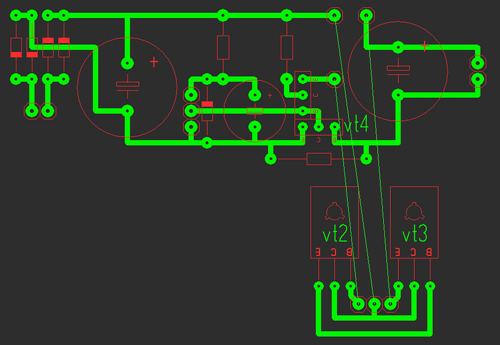
It consists of two parts: the stabilizer and protection are assembled on the first, and the power part on the second.
All parts are mounted on the main board (except for power transistors), transistors VT2 are soldered to the second board, VT3 are mounted on a radiator using thermal paste, it is unnecessary to isolate cases (collectors). Photos of the two blocks are shown below With a large 2A radiator and a small 0.6A.

Indication
Voltmeter: for it we need a 10k resistor and a 4.7k variable and I took the indicator m68501 but another one is possible. From the resistors we will assemble a divider, a 10k resistor will not allow the head to burn out, and with a 4.7k resistor we will set the maximum deviation of the arrow.
After the divider is assembled and the indication works, you need to calibrate it, for this we open the indicator and stick clean paper on the old scale and cut it out along the contour, it is most convenient to cut the paper with a blade.

When everything is glued and dry, we connect the multimeter in parallel to our indicator, and all this to the power supply, mark 0 and increase the voltage to volts, mark, etc.
Ammeter: for it we take a resistor of 0.27 ohm!!! and variable at 50k, the connection diagram is below, with a 50k resistor we set the maximum deviation of the arrow.
The graduation is the same, only the connection changes, see below, as a load, a 12 V halogen bulb is ideal.
| Designation | Type | Denomination | Quantity | Note | Shop | My notepad |
|---|---|---|---|---|---|---|
| VT1 | bipolar transistor | KT315B | 1 | To notepad | ||
| VT2, VT4 | bipolar transistor | KT815B | 2 | To notepad | ||
| VT3 | bipolar transistor | KT805BM | 1 | To notepad | ||
| VD1 | zener diode | D814D | 1 | To notepad | ||
| VDS1 | Diode bridge | 1 | To notepad | |||
| C1 | 100uF 25V | 1 | To notepad | |||
| C2, C4 | electrolytic capacitor | 2200uF 25V | 2 | To notepad | ||
| R2 | Resistor | 0.45 ohm | 1 | To notepad | ||
| R3 | Resistor | 1 kOhm | 1 | To notepad | ||
| R4 | Resistor |
Every radio amateur, whether he is a teapot or even a professional, should have a sedate and important power supply on the edge of the table. I currently have two power supplies on my desk. One delivers a maximum of 15 Volts and 1 Amp (black arrow), and the other 30 Volts, 5 Amps (right):
Well, there is also a self-made power supply:

I think you often saw them in my experiments, which I showed in various articles.
I bought factory power supplies a long time ago, so they cost me inexpensively. But, at the present time, when this article is being written, the dollar is already breaking through the mark of 70 rubles. Crisis, his mother, has everyone and everything.
Okay, something went wrong ... So what am I talking about? Oh yes! I think not everyone's pockets are bursting with money ... Then why don't we assemble a simple and reliable power supply circuit with our little hands, which will be no worse than a purchased block? Actually, our reader did just that. I dug up a schematic and assembled the power supply myself:

It turned out very even nothing! So, further on his behalf…
First of all, let's figure out what this power supply is good for:
- the output voltage can be adjusted in the range from 0 to 30 volts
- you can set some current limit up to 3 Amperes, after which the block goes into protection (a very convenient function, whoever used it knows).
– very low level of ripple (DC output of the power supply is not much different from DC batteries and accumulators)
– protection against overload and incorrect connection
- on the power supply by means of a short circuit (short circuit) of the “crocodiles”, the maximum allowable current is set. Those. current limit, which you set with a variable resistor on an ammeter. Therefore overloads are not terrible. The indicator (LED) will work, indicating that the set current level is exceeded.
So, now about everything in order. The scheme has been circulating on the Internet for a long time (click on the image, it will open in a new window in full screen):

The numbers in circles are the contacts to which you need to solder the wires that will go to the radio elements.
Designation of circles in the diagram:
- 1 and 2 to the transformer.
- 3 (+) and 4 (-) DC output.
- 5, 10 and 12 on P1.
- 6, 11 and 13 on P2.
- 7 (K), 8 (B), 9 (E) to transistor Q4.
Inputs 1 and 2 are supplied with an alternating voltage of 24 Volts from the mains transformer. The transformer must be of decent size so that it can deliver up to 3 Amperes to the load into a light one. You can buy it, or you can wind it).
Diodes D1 ... D4 are connected in a diode bridge. You can take diodes 1N5401 ... 1N5408 or some others that can withstand direct current up to 3 Amperes and above. You can also use a ready-made diode bridge, which would also withstand direct current up to 3 Amperes and above. I used the KD213 tablet diodes:

Chips U1,U2,U3 are operational amplifiers. Here is their pinout (pinout). View from above:

On the eighth output, “NC” is written, which indicates that this output does not need to be hooked anywhere. Neither a minus nor a plus of food. In the circuit, conclusions 1 and 5 also do not cling anywhere.
Transistor Q1 brand BC547 or BC548. Below is its pinout:

Transistor Q2 take better Soviet, brand KT961A

Don't forget to put it on the radiator.
Transistor Q3 brand BC557 or BC327

Transistor Q4 must be KT827!

Here is his pinout:

I didn’t redraw the circuit, so there are elements that can be confusing - these are variable resistors. Since the power supply circuit is Bulgarian, their variable resistors are designated as follows:
We have it like this:

I even pointed out how to find out its conclusions using the rotation of the column (twist).
Well, actually, the list of elements:
R1 = 2.2 kOhm 1W
R2 = 82 ohm 1/4W
R3 = 220 ohm 1/4W
R4 = 4.7 kOhm 1/4W
R5, R6, R13, R20, R21 = 10 kΩ 1/4W
R7 = 0.47 ohm 5W
R8, R11 = 27 kOhm 1/4W
R9, R19 = 2.2 kOhm 1/4W
R10 = 270 kOhm 1/4W
R12, R18 = 56kΩ 1/4W
R14 = 1.5 kOhm 1/4W
R15, R16 = 1 kΩ 1/4W
R17 = 33 ohm 1/4W
R22 = 3.9 kOhm 1/4W
RV1 = 100K multi-turn trimmer
P1, P2 = 10KOhm linear potentiometer
C1 = 3300uF/50V electrolytic
C2, C3 = 47uF/50V electrolytic
C4 = 100nF
C5 = 200nF
C6 = 100pF ceramic
C7 = 10uF/50V electrolytic
C8 = 330pF ceramic
C9 = 100pF ceramic
D1, D2, D3, D4 = 1N5401…1N5408
D5, D6 = 1N4148
D7, D8 = 5.6V zener diodes
D9, D10 = 1N4148
D11 = 1N4001 diode 1A
Q1 = BC548 or BC547
Q2 = KT961A
Q3 = BC557 or BC327
Q4 = KT 827A
U1, U2, U3 = TL081, operational amplifier
D12 = LED
Now I will tell you how I collected it. The transformer has already taken ready from the amplifier. The voltage at its outputs was about 22 volts. Then he began to prepare the case for my PSU (power supply)

pickled


laundered the toner

drilled holes:

I soldered the cribs for the op amps (operational amplifiers) and all other radio elements, except for two powerful transistors (they will lie on the radiator) and variable resistors:

And this is what the board looks like with the full installation:

We prepare a place for a scarf in our case:

We attach a radiator to the case:

Do not forget about the cooler that will cool our transistors:

Well, after locksmith work, I got a very pretty power supply. So what do you think?

I took the description of the work, the signet and the list of radio elements at the end of the article.
Well, if anyone is too lazy to bother, then you can always buy a similar kit of this scheme for a penny on Aliexpress at this link


For radio amateurs, and indeed a modern person, an indispensable thing in the house is the power supply unit (PSU), because it has a very useful function - voltage and current regulation.
At the same time, few people know that it is quite possible to make such a device with due diligence and knowledge of radio electronics with your own hands. For any radio amateur who likes to tinker with electronics at home, homemade laboratory power supplies will allow you to pursue your hobby without restrictions. Just about how to make an adjustable type of power supply with your own hands, our article will tell.
A power supply with current and voltage regulation in a modern home is a necessary thing. This device, thanks to its special device, can convert the voltage and current available in the network to the level that a particular electronic device can consume. Here is an approximate scheme of work, according to which you can make a similar device with your own hands.
But ready-made PSUs are expensive enough to buy them for specific needs. Therefore, today very often converters for voltage and current are made by hand.
Note! Homemade laboratory power supplies can have different dimensions, power ratings and other characteristics. It all depends on what kind of converter you need and for what purposes.
Professionals can easily make a powerful power supply, while beginners and hobbyists can start with a simple type of device. In this case, the scheme, depending on the complexity, can be used very different.

The regulated power supply is a universal converter that can be used to connect any household or computing equipment. Without it, no home appliance will be able to function normally.
Such a PSU consists of the following components:
The diagram above shows all the components of the instrument.
In addition, this type of power supply must have protection for high and low current. Otherwise, any abnormal situation may cause the converter and the electrical device connected to it to simply burn out. This result can also be caused by incorrect soldering of the board components, incorrect connection or installation.
If you are a beginner, then in order to make an adjustable type of power supply with your own hands, it is better to choose a simple assembly option. One simple type of converter is the 0-15V PSU. It has protection against exceeding the current in the connected load. The diagram for its assembly is located below.

Simple Assembly Diagram
This is, so to speak, a universal assembly type. The scheme here is available for understanding to any person who at least once held a soldering iron in his hands. The advantages of this scheme include the following points:

Diode bridge
In this situation, the transformer will provide a voltage in the range of 3V more than the maximum required voltage for the output. It follows from this that a power supply capable of regulating voltage up to 20V needs a transformer of at least 23V.
Note! The diode bridge should be selected based on the maximum current indicator, which will be limited by the available protection.
A 4700 microfarad filter capacitor will allow equipment that is sensitive to power interference not to give a background. This will require a compensation stabilizer with a ripple suppression ratio of more than 1000.
Now that we have dealt with the main aspects of the assembly, we need to pay attention to the requirements.
To create a simple, but at the same time high-quality and powerful power supply with the ability to regulate voltage and current with your own hands, you need to know what requirements exist for this type of converter.
These specifications look like this:
To fulfill the first requirement, you should use an integral stabilizer in your work. In the second case, the output must be made after the diode bridge, so to speak, bypassing the stabilizer.
![]()
Transformer TS-150–1
Once you have decided on the requirements that your stand-alone regulated type power supply must meet, and a suitable circuit has been selected, you can begin the assembly itself. But first of all, let's stock up on the details we need.
For assembly you will need:
After that, according to the scheme, we assemble an adjustable power supply with our own hands in strict accordance with all the recommendations. The sequence of actions must be followed.

Ready PSU
The following parts are used to assemble the PSU:
Note! Since the D814 zener diode takes exactly half the output voltage, it should be chosen to create a 0-25V output voltage of about 13 V.

Assembly Parts
To accommodate all parts, you must select a steel case. He will be able to shield the transformer and the power supply board. As a result, you will avoid the occurrence of various kinds of interference for sensitive equipment.
The resulting converter can be safely used to power any household equipment, as well as experiments and tests carried out in the home laboratory. Also, such a device can be used to assess the performance of a car generator.
Using simple schemes for assembling an adjustable type of power supply, you can fill your hand and later make more complex models with your own hands. You should not take on overwork, because in the end you may not get the desired result, and the home-made converter will work inefficiently, which can negatively affect both the device itself and the functionality of the electrical equipment connected to it.
If everything is done correctly, then at the output you will get an excellent power supply with voltage regulation for your home laboratory or other everyday situations.
 Choosing a street motion sensor to turn on the light
!
If you are looking for a simple and reliable linear power supply circuit, then this article is for you. Here you will find complete assembly instructions, as well as setting up this power supply. The author of this homemade product is Roman (YouTube channel "Open Frime TV").


And now, a couple of weeks after the order, we receive our long-awaited boards. Having opened the package and examined the boards closer, we can make sure that everything turned out very high quality and beautifully.


And now let's move on to a detailed examination of the circuit and the board itself. You can see the scheme on your screens.


Then we begin to slowly rotate the variable resistor.


